Why You Should Care How It Works
I get this question surprisingly often at trade shows: “I don’t need to know how it works—just tell me what it does.”
That attitude has cost more shops more money than I can quantify.
Here’s what I’ve seen happen when operators don’t understand the mechanics of their beveling machine:
- They set feed rates by guessing instead of reasoning—and burn through $200 inserts in half their rated life
- They blame the machine for chatter marks when the real problem is a loose mandrel they didn’t know how to check
- They buy an OD-mount machine when an ID-mount would have been half the price and twice as fast for their pipe size
I’ve been building and selling pipe beveling machines for over 15 years. The operators who understand how the machine works—even at a basic level—consistently get better results, break fewer tools, and make smarter purchasing decisions. That’s not opinion. That’s pattern recognition from thousands of customer interactions.
You don’t need an engineering degree. You need about 10 minutes.
The Core Principle in 30 Seconds
Every beveling machine—whether it costs $500 or $50,000, whether it’s portable or stationary, whether it cuts pipe or plate—works on the same fundamental principle:
A motor spins a cutting tool around (or along) the workpiece edge at a controlled speed and angle to remove metal and create a precise bevel geometry.
That’s it. Whether you’re looking at a $3,000 handheld unit or a $50,000 production machine, the underlying physics is identical. Everything else is engineering detail about how that spinning and cutting is delivered. But those details matter enormously for your results, so let’s break them down.
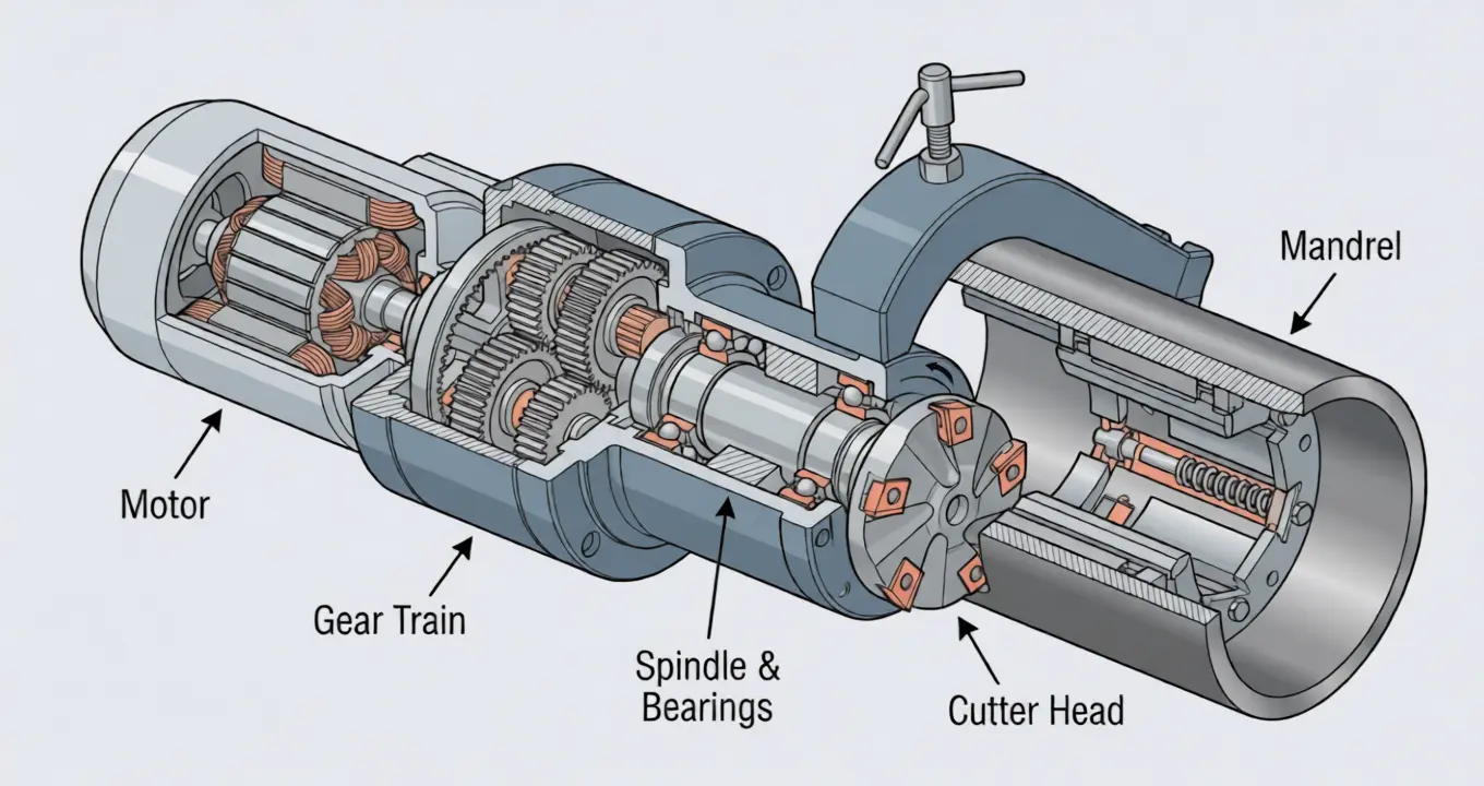
Inside the Machine: What Each Part Actually Does
Let me walk through the anatomy of a typical pipe beveling machine, from power source to cutting edge. I’ll use our ISE T-Model as a reference since it’s our most popular series, but the principles apply to virtually every brand.
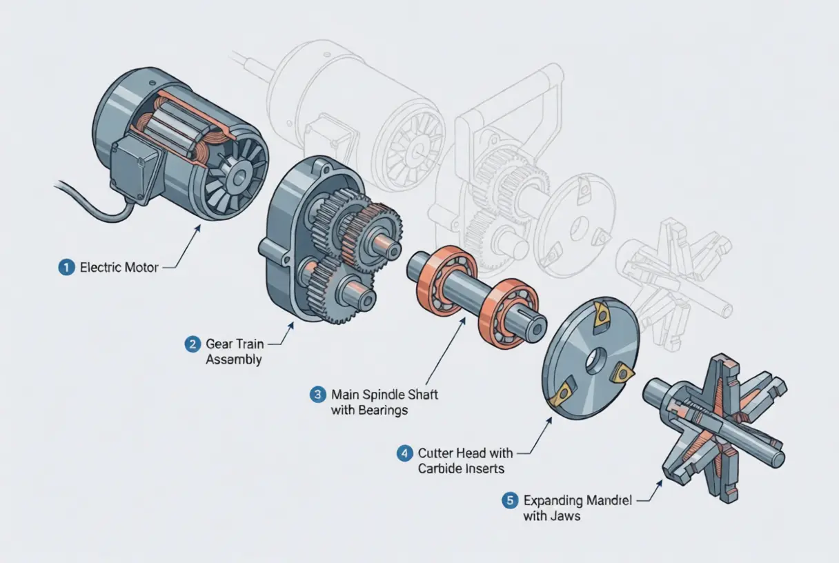
1. The Motor (Power Source)
The motor converts electrical energy (or compressed air, or hydraulic pressure) into rotational force. In most portable beveling machines, this is either:
- An electric motor (500W–2,000W typically)
- A pneumatic motor (air-driven, common in hazardous environments)
- A hydraulic motor (for heavy-duty stationary machines)
What matters to you: The motor determines your maximum torque—which directly limits how thick and how hard a material you can cut. An underpowered motor on thick-wall chrome-moly isn’t just slow. It stalls, deflects the cutter, and produces garbage surface finish.
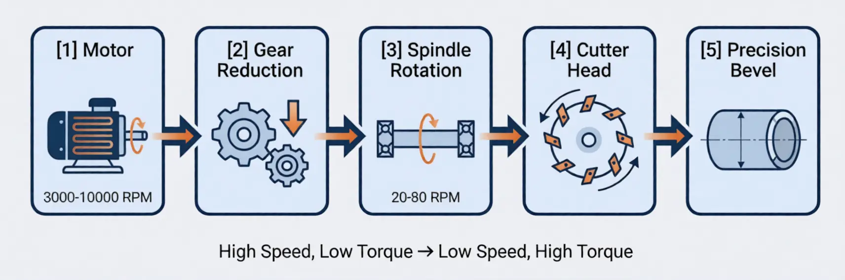
2. The Gear Train (Speed Reduction)
The motor spins fast—typically 3,000-10,000 RPM. The cutter head needs to spin much slower—typically 20-80 RPM for pipe beveling. The gear train converts high-speed, low-torque motor output into low-speed, high-torque cutter head rotation.
Why this matters: Gear quality directly determines vibration and surface finish. Cheap gears = vibration = chatter marks on your bevel = welder complaints. This is the component where you really feel the difference between a $2,000 machine and a $5,000 machine.
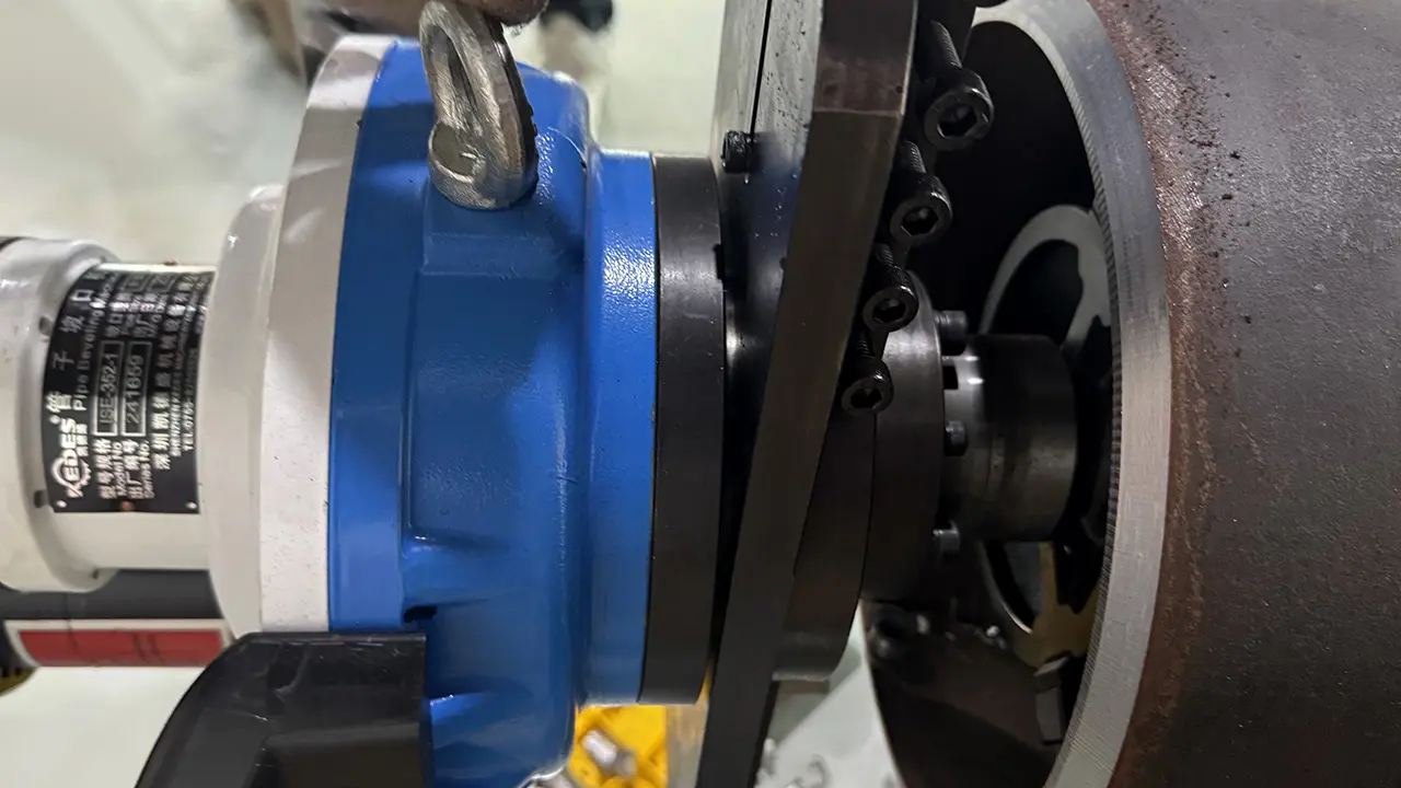
3. The Spindle
The central rotating shaft that transfers power from the gear train to the cutter head. The spindle bearings are the heart of the machine’s precision—they determine how accurately the cutter head tracks around the pipe.
What I tell operators: If your machine suddenly starts producing inconsistent bevels after months of good performance, check the spindle bearings first. Nine times out of ten, that’s where the problem is.
4. The Cutter Head (Tool Holder)
The cutter head holds the cutting inserts at the correct bevel angle and rotates them around (or along) the workpiece. This is where the actual metal removal happens.
Most modern machines use indexable carbide inserts—replaceable cutting tips that you rotate to a fresh edge when one wears out, rather than resharpening. The cutter head geometry determines:
- Bevel angle — fixed or adjustable depending on the machine
- Number of cuts per revolution — more inserts = smoother finish
- Chip clearance — how effectively metal chips are evacuated from the cutting zone
5. The Clamping/Mounting System
This is what holds the machine in position relative to the workpiece. For pipe machines, it’s either:
- An expanding mandrel (ID-mount) — inserts into the pipe bore and expands to grip the inner wall
- A chain or jaw clamp (OD-mount) — wraps around the outside of the pipe
- A chuck or collet (stationary machines) — holds the pipe while the machine stays fixed
This is the most overlooked component. I’ve seen operators spend 20 minutes troubleshooting bevel inconsistency, checking inserts, checking feed rates—when the actual problem was a mandrel that wasn’t fully expanded and the machine was wobbling 0.5mm on each revolution.
How the Cutting Process Actually Happens
Now let’s put it all together. Here’s the step-by-step sequence of what happens when you press the start button:
Step 1: Mounting and Alignment
The machine is clamped to the pipe (or the pipe is loaded into the machine for stationary units). The critical dimension here is concentricity—the cutter head must rotate perfectly centered relative to the pipe axis. Any offset here shows up as uneven wall thickness in the bevel.
Step 2: Cutter Engagement
The operator advances the cutter head toward the pipe end until the inserts make contact. On most machines, this is a manual feed wheel or lever. On CNC stationary machines, it’s automatic.
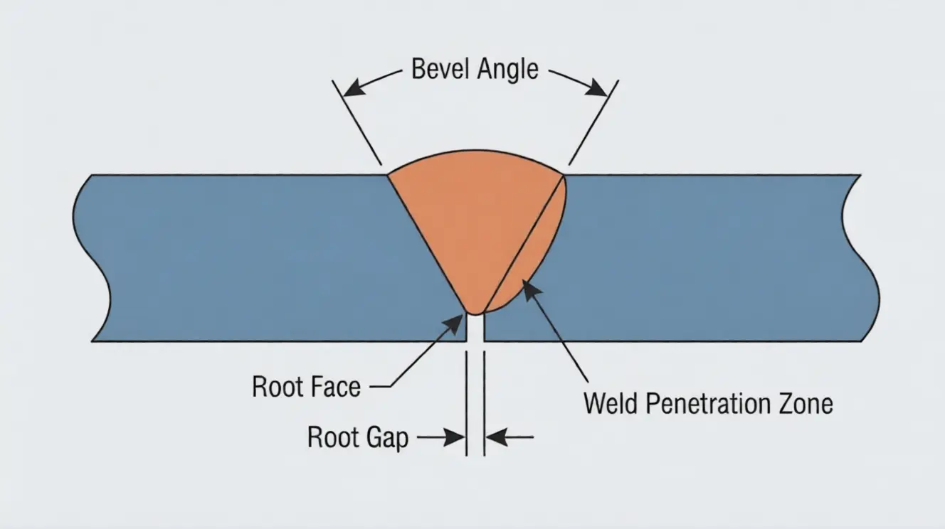
Key concept: depth of cut. Each pass removes a specific amount of material—typically 0.5–2mm per pass for cold cutting. Taking too deep a cut overloads the inserts, causes chatter, and can stall the machine. Taking too shallow a cut wastes time. The right depth of cut depends on:
- Material hardness (carbon steel vs stainless vs chrome-moly)
- Wall thickness
- Machine power
- Insert geometry
Step 3: Rotational Cutting
The cutter head rotates around the pipe circumference. Each insert takes a small bite of metal as it passes. The combined bites from all inserts on the cutter head produce a smooth, continuous bevel surface.
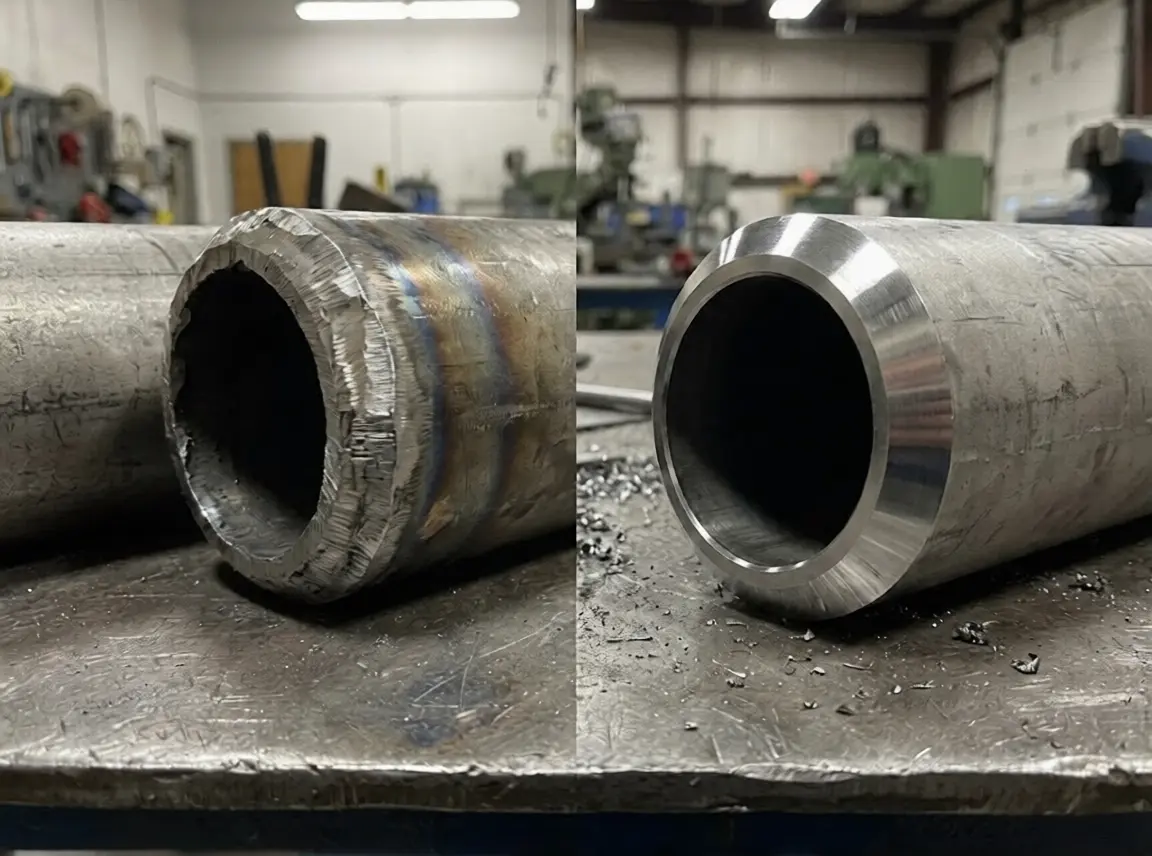
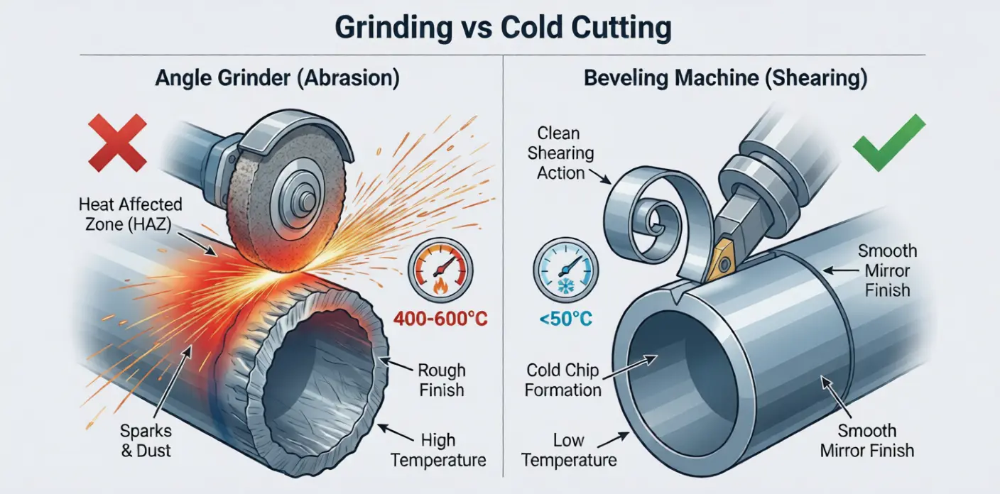
This is fundamentally different from grinding. An angle grinder removes material by abrasion—rubbing an abrasive wheel against the surface at high speed, generating heat and a rough finish. A beveling machine removes material by shearing—a sharp cutting edge cleanly separates a chip from the parent metal, like a lathe cutting a shaft.
This shearing action is why beveling machines produce:
- No heat-affected zone (cold cutting)
- Smooth surface finish (machined, not ground)
- Consistent geometry (mechanically guided, not hand-held)
Step 4: Multiple Passes (If Needed)
For thick-wall pipe or compound bevel profiles, the operator makes multiple passes, advancing the depth of cut incrementally. Each pass removes another layer until the final bevel geometry is achieved.
For J-prep bevels (curved profile), the cutter head uses specially shaped inserts that create the curved geometry in a single pass—something that’s physically impossible with an angle grinder and extremely difficult even with a standard flat insert.
Step 5: Completion
Once the bevel reaches the specified angle and root face dimension, the operator retracts the cutter and removes the machine. The bevel is ready for welding—no grinding, no cleanup, no secondary operations.
Total cycle time: On a typical 8” Schedule 40 carbon steel pipe, the entire process takes 3-8 minutes. Compare that to 25-40 minutes with an angle grinder, and you understand why shops that switch never go back.
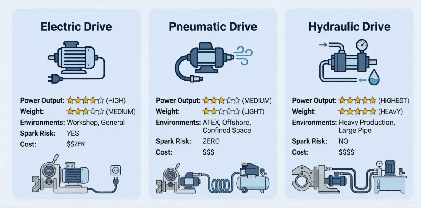
Three Drive Types and Why They Matter
Not all motors are interchangeable. The drive type determines where and how you can use the machine.
Electric Drive
How it works: Standard electric motor powered by mains electricity (110V/220V) or battery.
Best for:
- Workshop environments with reliable power
- General-purpose pipe and plate beveling
- Maximum power-to-weight ratio
Limitation: Can’t be used in ATEX/explosive atmospheres (oil & gas, chemical plants). Spark risk.
Our electric machines: Most of our pipe beveling series come in electric variants, including the ISE T-Model and DCM Stationary.
Pneumatic (Air) Drive
How it works: Compressed air spins a vane motor or turbine. Requires 6-8 bar shop air supply.
Best for:
- Hazardous environments (zero spark risk)
- Confined spaces (no electrical hazard)
- Offshore and petrochemical sites
Limitation: Requires a compressor and air lines. Lower power-to-weight ratio than electric. Sensitive to moisture in the air supply—wet air kills pneumatic motors.
What I always tell customers: If you’re buying pneumatic for a field application, invest in a proper air dryer and filter. I’ve seen $8,000 pneumatic machines destroyed by water in the air line within 6 months.
Hydraulic Drive
How it works: Pressurized hydraulic fluid drives a motor. Used primarily on heavy-duty stationary machines and large split-frame cutters.
Best for:
- Very large pipe diameters (24”+)
- Heavy wall thickness (30mm+)
- Continuous duty in production environments
Limitation: Heaviest and most complex system. Requires hydraulic power unit. Not practical for portable applications under 16”.
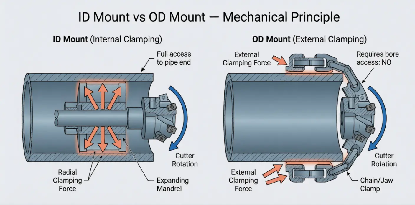
ID Mount vs OD Mount: The Mechanical Difference
This is the question I answer most often, and most people get the explanation wrong. They focus on pipe size. The real difference is mechanical.
ID-Mount (Internal Mounting)
The machine inserts an expanding mandrel into the pipe bore. The mandrel expands radially to grip the inner wall, creating a rigid, centered mounting point. The cutter head then rotates around the pipe’s outer edge.
Mechanically, this is superior because:
- The mandrel creates a concentric reference point — the cutter automatically tracks true to the pipe axis
- The pipe exterior is completely unobstructed — the cutter head has full access to the end face
- Clamping force is distributed evenly around the bore
Our ID-mount machines include: ISE T-Model, ISE II-Model, ISC Block Type
OD-Mount (External Mounting)
The machine clamps around the outside of the pipe using chains, jaws, or a split-frame ring. The cutter head rotates inside the clamped ring.
When you need this:
- Pipe is already installed (no bore access)
- Pipe ends are damaged or out of round (mandrel can’t expand properly)
- Cutting AND beveling in one setup (split-frame machines)
Our OD-mount machines include: Split Frame, CAM Type
The honest bottom line: If you have bore access and reasonably round pipe, ID-mount is faster, more precise, and usually cheaper. If you don’t have bore access, OD-mount is your only option. For a detailed decision framework, see our ID vs OD Mount guide.
Portable vs Stationary: Different Engineering, Same Principle
The cutting principle is identical. The engineering is completely different.
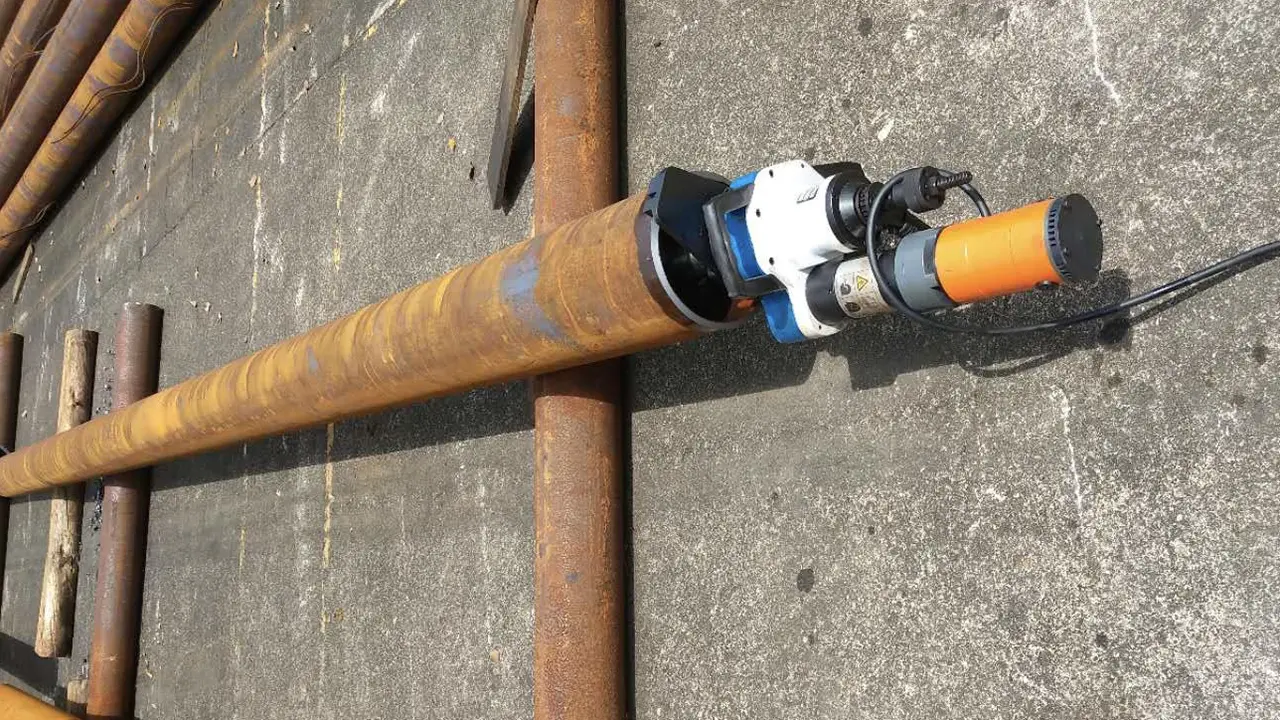
Portable Machines
Designed to go to the pipe. Lightweight (5–50 kg), self-contained, battery or cord-powered. The machine mounts on the workpiece and the cutter rotates around it.
Engineering trade-offs:
- Lighter = less rigid = more sensitive to setup quality
- Smaller motors = lower material removal rate
- Manual feed = operator-dependent consistency
Best for: Field work, installed piping, small-to-medium batches, diverse pipe sizes.
Stationary Machines
The pipe goes to the machine. Heavy (200–2,000+ kg), bolted to the shop floor, powered by large motors. The pipe is held in a chuck or clamp while the machine’s cutter head does the work.
Engineering advantages:
- Massive rigidity = extremely tight tolerances
- Powerful motors = fast cycle times on thick walls
- Automatic feed = perfectly repeatable results
- CNC control (on advanced models) = compound profiles in one setup
Best for: Production environments with 50+ bevels per shift, tight tolerances, heavy wall pipe.
Our DCM Stationary series is designed for exactly this scenario—high-volume shops that need consistent, fast output. If you’re unsure which category fits your operation, our Portable vs Stationary guide walks through the decision logic.
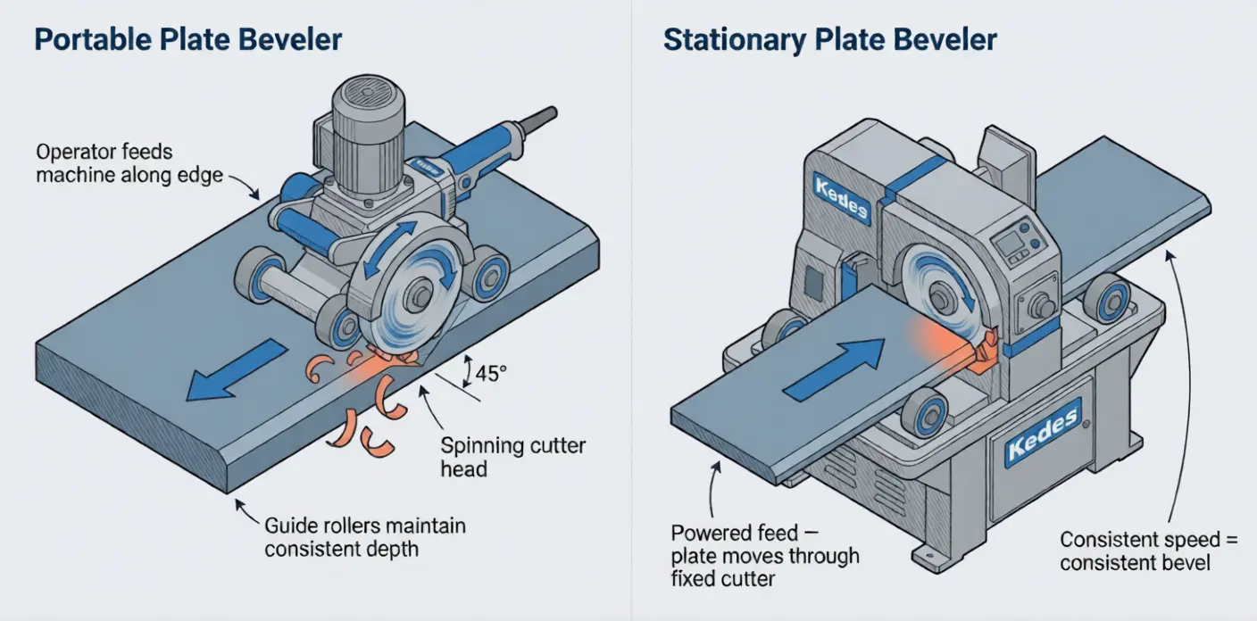
Plate Beveling Machines: A Different Approach
Everything above focused on pipe. Plate beveling works on the same cutting principle but with a fundamentally different motion.
Instead of a cutter rotating around a cylindrical workpiece, a plate beveling machine moves a spinning cutter along a flat edge. Think of it like a router running along the edge of a board—except it’s cutting hardened steel at a precise angle.
Portable Plate Bevelers
Handheld units like our SKF-15 or GL Plate Beveler ride along the plate edge on guide rollers. The operator feeds the machine manually, and the spinning cutter creates a consistent bevel.
Stationary Plate Bevelers
Production machines like our DMM-90X or DMM-900X Dual Spindle use powered feed systems to drive the plate through the machine. The cutter stays fixed; the workpiece moves.
Milling vs Rolling Shear
There are actually two different cutting methods for plate beveling:
- Milling type — A rotating cutter with multiple inserts shears the metal (same principle as pipe machines). Produces excellent surface finish. Our GL, DMM-90X, and traveling milling series use this method.
- Rolling shear type — A pair of angled rollers deform the plate edge into a bevel shape. Faster than milling but rougher surface finish. Our KBM series uses this method.
For a detailed comparison, see our Milling vs Rolling Shear guide.
What Goes Wrong (And Why Understanding Mechanics Prevents It)
Here’s where the “why should I care how it works” question gets answered in dollars. These are the five most common problems I see, and every single one is preventable with basic mechanical understanding.
1. Chatter Marks on the Bevel Surface
What it looks like: Visible ridges or wave patterns on the bevel face.
What’s actually happening: The cutter is vibrating relative to the workpiece. This can be caused by:
- Loose mandrel (machine isn’t rigid on the pipe)
- Worn spindle bearings (play in the rotating assembly)
- Excessive depth of cut (overloading the inserts)
- Worn or chipped inserts (uneven cutting forces)
The fix: Check mounting rigidity first, then bearings, then reduce depth of cut, then inspect inserts. In that order.
2. Inconsistent Bevel Angle Around the Circumference
What it looks like: One side of the bevel is 30°, the other side is 33°.
What’s actually happening: The machine isn’t centered on the pipe axis. Either:
- The mandrel isn’t fully expanded (most common)
- The pipe is severely out of round
- The cutter head has a bent component
The fix: Re-expand the mandrel and verify concentricity. If the pipe is out of round by more than 1-2%, consider an OD-mount machine that clamps to the actual shape.
3. Root Face Variation
What it looks like: The thin flat section at the bottom of the bevel varies from 0.5mm to 2.5mm around the pipe.
What’s actually happening: Same as inconsistent angle—it’s a concentricity problem. But it can also be caused by inconsistent wall thickness in the pipe itself (especially on seamless pipe), which no machine can compensate for.
The fix: Check concentricity first. If the pipe wall thickness varies, this is a pipe quality issue. Flag it to your QC team.
4. Insert Life Way Below Expectations
What it looks like: Inserts lasting 50 bevels instead of the rated 200.
What’s actually happening (usually): Excessive feed rate or depth of cut is overloading the insert. The cutting edge chips instead of wearing gradually. Other causes:
- Wrong insert grade for the material (using carbon steel inserts on stainless)
- Cutting dry when the material needs lubrication
- Thermal shock from intermittent cutting
The fix: Follow the manufacturer’s recommended cutting parameters. I know “read the manual” sounds patronizing, but I’ve watched operators destroy $50 inserts because they were running at 2x the recommended depth of cut to “save time.”
5. Machine Stalls or Bogs Down
What it looks like: Motor slows dramatically, makes straining sounds, or trips the breaker.
What’s actually happening: The motor is being asked to deliver more torque than it can produce. Causes:
- Material is harder than expected (check the actual material grade)
- Depth of cut is too aggressive
- Inserts are dull (dull inserts require more force)
- On pneumatic machines: air supply pressure is too low
The fix: Reduce depth of cut, replace dull inserts, verify material grade, check air pressure.
The Bottom Line
A beveling machine is not complicated. Motor → gears → spindle → cutter head → bevel. That’s the entire machine in five components.
But here’s what separates operators who get consistent, high-quality results from those who fight their machines:
The good operators understand that rigidity, concentricity, and cutting parameters are the three things that determine bevel quality. Everything else—machine brand, price, country of origin—is secondary to these fundamentals.
- Rigidity — Is the machine solidly mounted? Is the mandrel fully expanded? Are the bearings in good condition?
- Concentricity — Is the cutter head rotating true to the pipe axis? Is the mounting aligned?
- Cutting parameters — Are you using the right depth of cut, feed rate, and insert grade for your material?
Get those three things right, and virtually any decent beveling machine will produce good results. Get them wrong, and the most expensive machine in the world will produce garbage.
Ready to choose the right machine for your application?
Start with the fundamentals: What Is Pipe Beveling? — If this article was useful, the fundamentals guide fills in the “why” behind the bevel geometry.
Choosing a mounting type? ID Mount vs OD Mount: Why 80% of Buyers Pick Wrong — The mechanical differences explained above in full detail.
Field vs workshop? Portable vs Stationary Beveling Machine — Match the machine engineering to your actual work pattern.
Browse all machines: See our full range of pipe bevelers | Plate Beveling Machines
Need specific advice? Tell me your pipe size, material, and application and I’ll recommend exactly what you need—even if it’s not one of ours.