The $80,000 Lesson
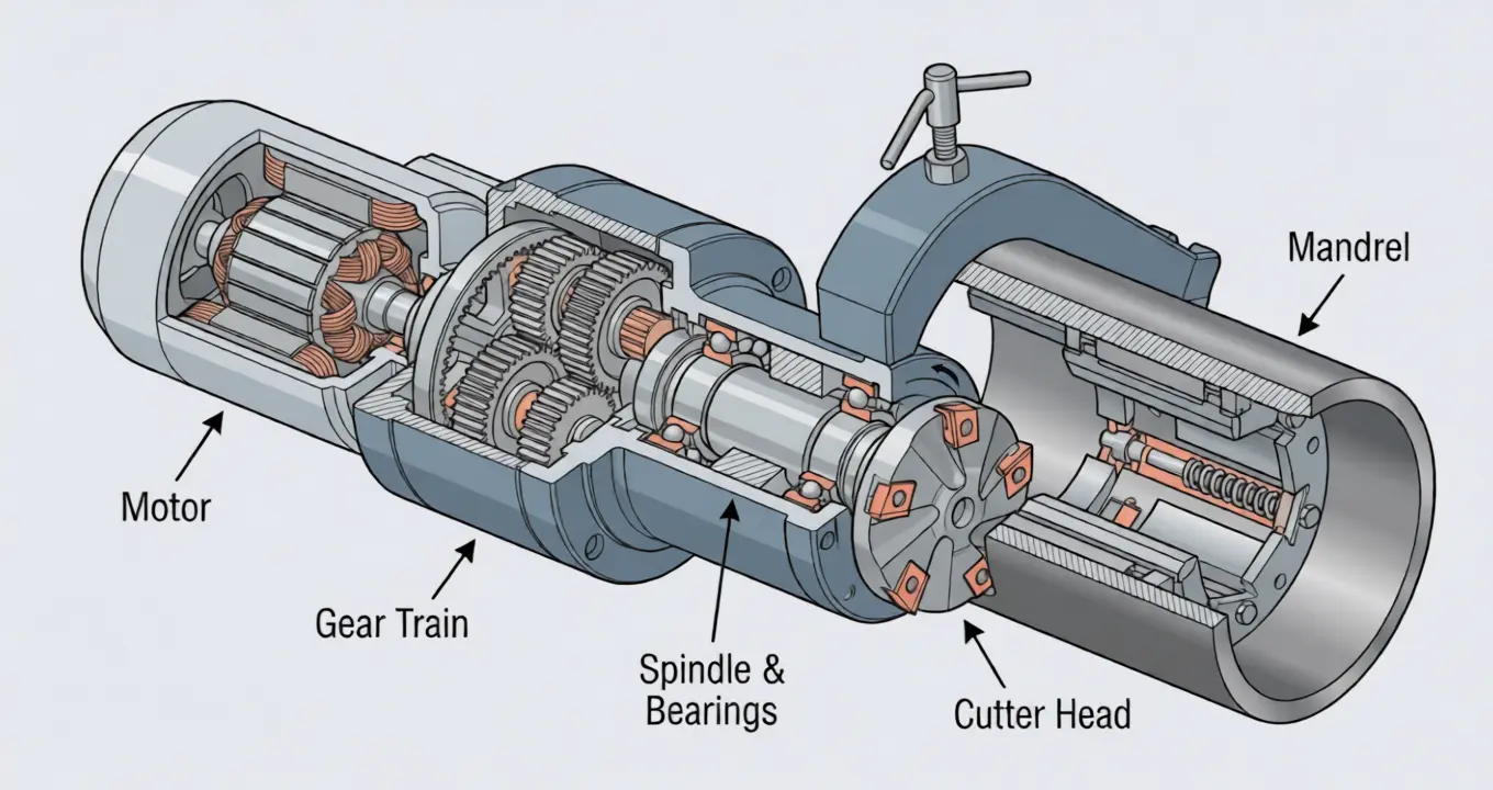
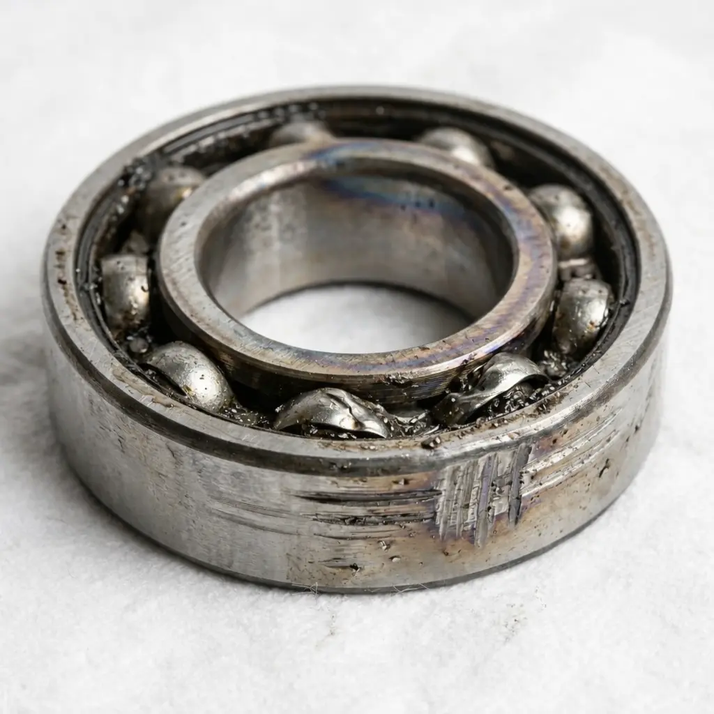
Last year, a shipyard in Turkey called me in a panic. Their DCM stationary beveling machine had seized mid-production. The spindle bearings had failed catastrophically—metal fragments contaminated the gear train, scored the spindle housing, and destroyed the cutter head assembly. Total repair cost: $12,000 in parts, plus three weeks of downtime on a production line that was billing $3,200 per day.
Total damage: roughly $80,000.
When I asked to see their maintenance log, the foreman looked at me like I’d asked for his diary. There was no maintenance log. No scheduled checks. The machine ran three shifts a day for 14 months without anyone so much as checking the gear oil level.
The bearing that failed? It showed warning signs for at least two months—noise, vibration, slight temperature increase on the housing. Any operator trained to spend 15 minutes per week checking the basics would have caught it at the $200 bearing replacement stage instead of the $80,000 catastrophic failure stage.
I’m not telling this story to sell you spare parts. I’m telling it because I see this exact scenario play out 3-4 times a year, across every brand—not just ours. Whether it’s a portable pipe beveling machine or a heavy-duty plate beveler, the failure pattern is identical. And every single time, it was preventable.
Why Most Maintenance Guides Are Useless
I’ve read the maintenance manuals from every major beveling machine manufacturer—including our own. Most of them are 40 pages of obvious advice that nobody follows:
- “Lubricate regularly” — How regularly? With what? Where exactly?
- “Inspect for wear” — What does wear look like? How much is too much?
- “Replace parts as needed” — Needed according to whom? How do I know before it breaks?
The problem isn’t that operators don’t care about maintenance. The problem is that nobody gives them a concrete, time-boxed routine they can actually follow during a real production schedule.
So here it is. The exact maintenance routine I walk through with every customer during machine commissioning—whether they’re running our pipe bevelers on a pipeline project or our plate beveling equipment in a structural steel shop. It takes 15 minutes per week for the basic checks, and 30 minutes per month for the deep checks. If you do nothing else, do this.
The 15-Minute Weekly Routine
Do this every Friday afternoon (or whenever your weekly production cycle ends). Set a timer. You’ll finish before it goes off.
Minute 0-3: Visual Inspection
What you’re looking for: anything that wasn’t there last week.
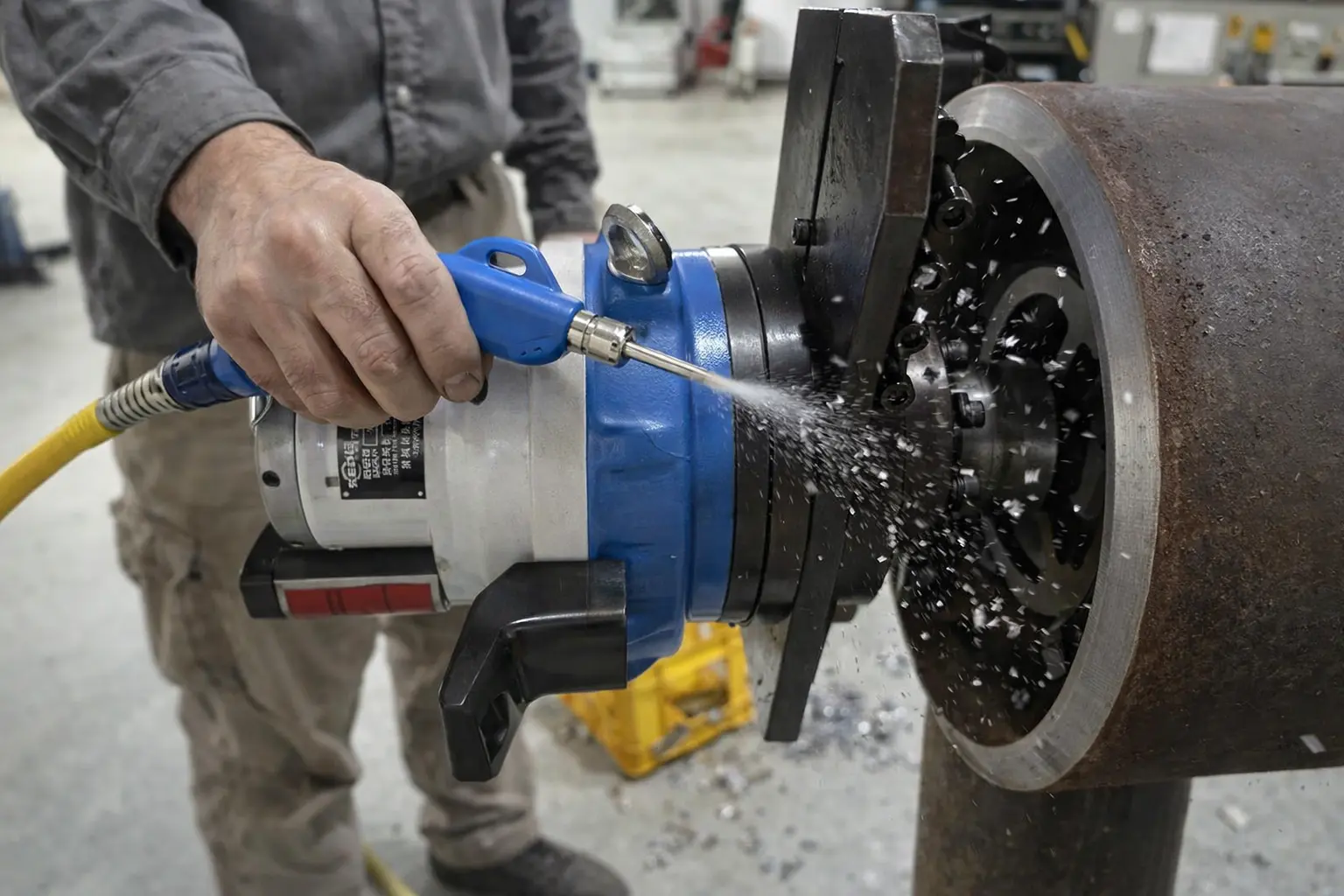
- Chip buildup around the cutter head, mandrel, and gear housing — compressed air blow-off or brush clean
- Oil or grease leaks — any wet spots on the housing, base, or around seals that shouldn’t be there
- Loose fasteners — give each external bolt a quick check with your hand. If anything feels loose, torque it properly
- Cable/hose condition (electric: power cord; pneumatic: air lines) — look for kinks, cracks, exposed wiring
This applies to every machine type — from a handheld pipe beveler to a 500kg plate milling machine. The inspection points are the same; only the machine size changes.
What this catches: 40% of failures start with chip contamination or loose fasteners. Five seconds of looking saves five hours of repair.
Minute 3-6: Mandrel and Clamping System
This is the component most operators ignore—and the one that causes the most quality problems.
For ID-mount machines (ISE T-Model, ISE II, ISC Block Type):
- Expand and retract the mandrel fully 2-3 times — movement should be smooth, no sticking or grinding
- Check mandrel jaws for scoring or galling — rough surfaces mean the jaws are wearing unevenly
- Wipe the mandrel cone and jaws with a clean cloth — metal chips trapped here cause misalignment
For OD-mount machines (Split Frame, CAM Type):
- Inspect chain links or jaw surfaces for wear, deformation, or contamination
- Check the clamping mechanism for smooth operation—no hesitation or catching
- Clean the clamping surfaces
What this catches: Mandrel issues account for about 30% of all bevel quality complaints I deal with. A sticking mandrel means the machine isn’t centered—which means inconsistent bevel angles, and your welder blames the machine when the real problem is 15 seconds of cleaning you skipped.
Minute 6-9: Cutter Head and Inserts
- Remove the cutter head cover (if applicable) and blow out chips
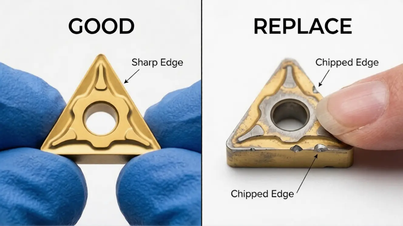
- Inspect each carbide insert — look for chipping on the cutting edge, not just overall wear. A chipped insert produces a rough surface finish and increases cutting forces by 30-50%
- Check insert seating — each insert should sit flat in its pocket with no gaps. Loose inserts vibrate, chip faster, and can eject at speed (this is a safety issue, not just a performance issue)
- Finger-test the insert screws — they should be snug. Don’t overtorque; just verify they haven’t backed out from vibration
Rule of thumb for insert replacement: If you can feel the chip with your fingernail running across the cutting edge, it’s time to index to a fresh edge. Don’t wait until the insert is visibly damaged—by then, you’ve been producing subpar bevels for days.
Minute 9-12: Gear Oil and Lubrication
- Check gear oil level through the sight glass or inspection port — top up if low. If you don’t know where the sight glass is, find it now. On most of our machines, it’s on the side of the gear housing
- Check oil color — fresh gear oil is amber/golden. If it’s dark brown or black, it needs changing (see Monthly Checks). If it’s milky, water has gotten in—change it immediately
- Grease the mandrel mechanism (2-3 pumps of lithium grease on machines with grease fittings)
- Lubricate the feed mechanism — a light wipe of machine oil on the feed screw and guide rails
What oil to use: ISO VG 68 or VG 100 gear oil for the gear housing. Lithium-based EP2 grease for mandrel and bearing grease points. If in doubt, contact us with your machine model and we’ll specify exactly what you need.
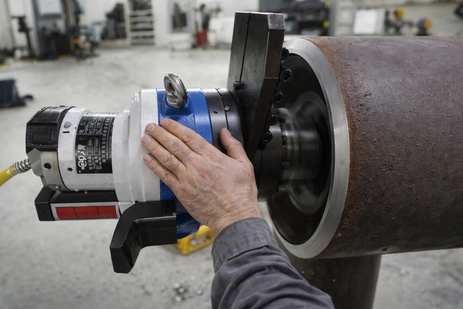
Minute 12-15: Function Test
- Run the machine unloaded for 30 seconds — listen for unusual noise (clicking, grinding, whining that wasn’t there before)
- Check for vibration — place your hand on the housing. Healthy machines have a smooth hum. Sick machines have a pulse or rattle
- Verify feed mechanism — advance and retract the feed. It should be smooth and consistent
- Temperature check — after 30 seconds of running, the gear housing should be warm, not hot. If you can’t hold your hand on it comfortably, something is generating excess friction
The sound test is the most valuable diagnostic tool you have. I can diagnose 80% of beveling machine problems over a phone call just by listening. Train your operators to know what “normal” sounds like for their specific machine. When the sound changes, something has changed mechanically.
Carbide Insert Replacement: The #1 Skill Most Operators Get Wrong
I want to spend extra time on this because carbide inserts are the single highest-cost consumable on any beveling machine, and most operators are either replacing them too early (wasting money) or too late (wasting quality and damaging the machine).
The Four Stages of Insert Wear
| Stage | What It Looks Like | What to Do |
|---|---|---|
| 1. Fresh edge | Sharp, clean cutting edge with factory coating visible | Run it |
| 2. Normal wear | Slight wear flat on the cutting edge, coating partially worn through. Surface finish still good | Keep running. This is the productive life of the insert |
| 3. Edge deterioration | Small chips visible on cutting edge, increased cutting noise, surface finish roughening | Index to fresh edge now. You’re past the optimal point |
| 4. Failure | Large chips or fracture, severe noise, poor surface finish, increased machine vibration | You’ve gone too far. The damaged insert has been overloading the machine and damaging adjacent inserts |
The critical mistake: Most operators run inserts from Stage 1 straight into Stage 4 because Stage 2 and Stage 3 look similar to the untrained eye. The fingernail test catches Stage 3 before it becomes Stage 4.
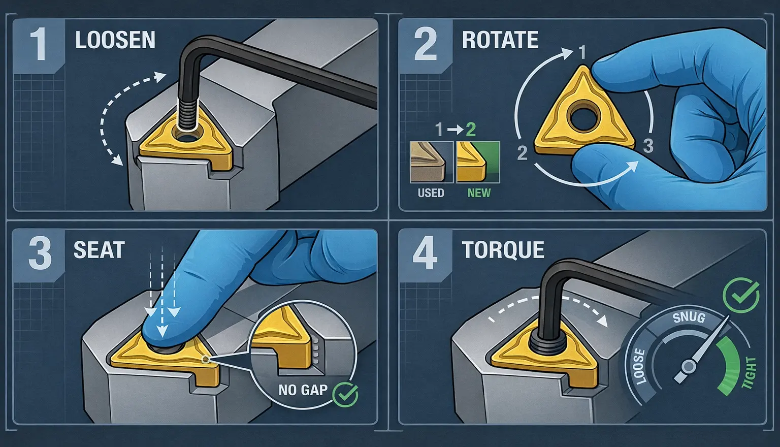
How to Index and Replace Inserts Correctly
- Power off the machine. This sounds obvious, but I’ve watched operators change inserts with the power connected. Don’t.
- Loosen the insert screw — counterclockwise, one turn. Don’t remove it completely.
- Rotate the insert to the next fresh edge (most inserts have 3 or 4 usable edges, indicated by the number of sides)
- Seat the insert — press it flat into the pocket. Verify there’s no chip debris under the insert
- Torque the screw — snug plus 1/8 turn. Overtorquing cracks the carbide. Undertorquing lets it vibrate loose
- Verify by hand — gently rotate the cutter head and confirm the insert doesn’t contact anything it shouldn’t
How many edges per insert? Most of our standard inserts are triangular (3 edges) or square (4 edges). When all edges are used, replace the entire insert. Don’t try to resharpen carbide inserts—the geometry is precision-ground at the factory, and field resharpening destroys it.
Insert Selection by Material
Using the wrong insert grade for your material is like using a butter knife on steak—it technically cuts, but you’ll destroy the tool and hate the result.
| Material Being Cut | Insert Grade | Coating | Notes |
|---|---|---|---|
| Carbon steel (A36, A572) | P-grade (P10-P30) | TiN or TiAlN | General purpose, longest life |
| Stainless steel (304, 316L) | M-grade (M10-M20) | TiAlN | Must use with coolant/lubricant |
| Chrome-moly (P11, P22, P91) | P-grade (P20-P40) | TiAlN or AlCrN | Reduced speed, increased feed |
| Duplex stainless | M-grade (M20-M30) | AlCrN | Aggressive material—expect 40% shorter insert life |
| Inconel / exotic alloys | S-grade | Uncoated or TiAlN | Specialty application—contact us for recommendation |
What I tell every customer: When you order a machine, order the correct inserts for your primary material at the same time. I’ve seen operators use carbon steel inserts on stainless because “it’s what was in the machine” and burn through a $50 insert in 10 bevels instead of 150.
Monthly Deep Checks (30 Minutes)
Once a month, schedule 30 minutes for a more thorough inspection. This is where you catch the problems that the weekly routine can’t.
Gear Oil Change Assessment
- Check interval: Every 500 operating hours or 6 months, whichever comes first
- How to check: Drain a small sample from the drain plug into a clear container. Hold it up to the light
- Clear amber = good, keep running
- Dark but transparent = approaching change interval, schedule it
- Opaque black = change now
- Milky = water contamination, change immediately and find the leak
Gear oil change procedure:
- Run the machine for 5 minutes to warm the oil (warm oil drains completely)
- Remove drain plug, drain into appropriate container
- Replace drain plug with new gasket
- Fill through the fill port to the sight glass line
- Run unloaded for 2 minutes, recheck level
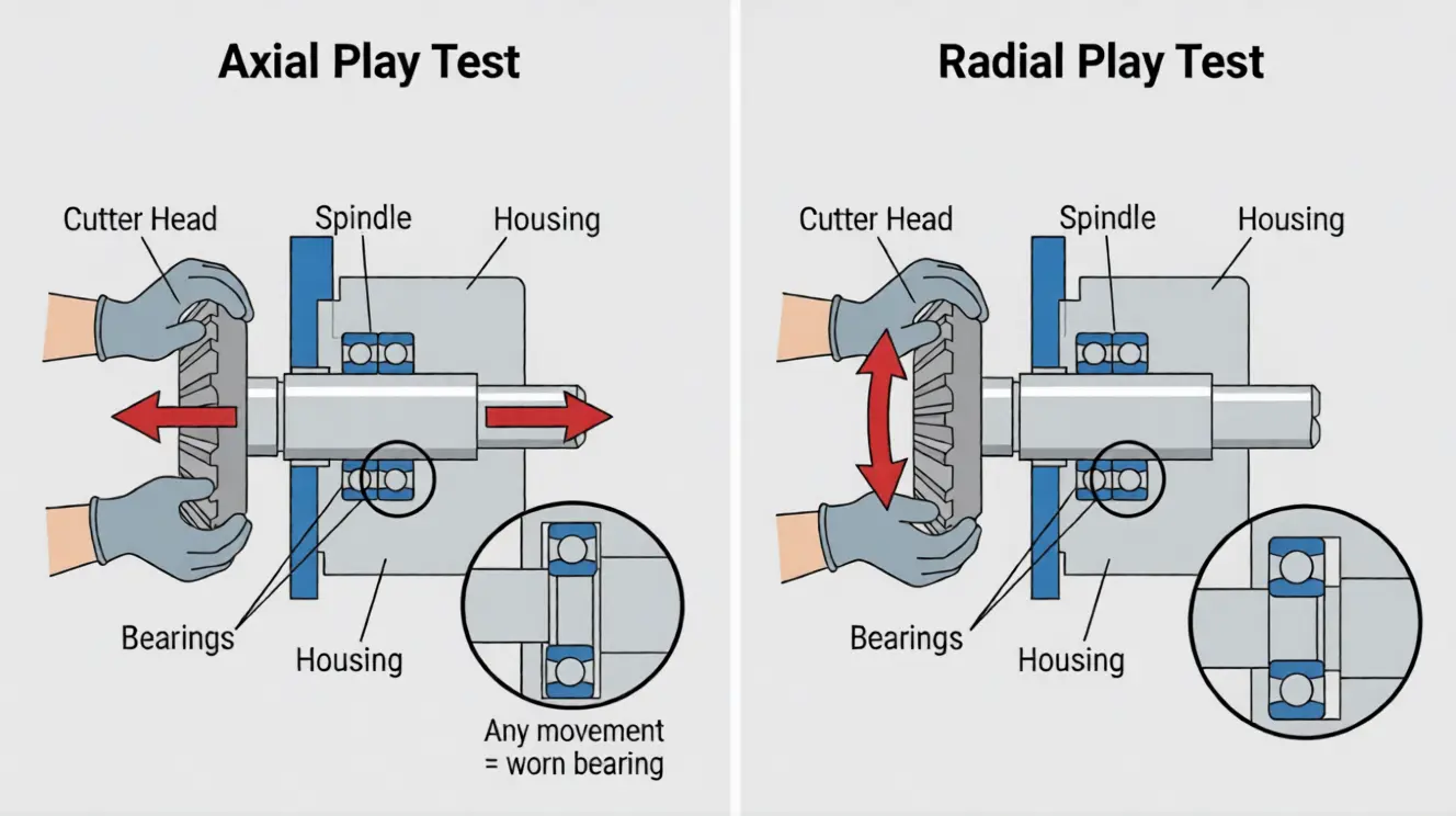
Spindle Bearing Assessment
This is the check that would have saved my Turkish shipyard customer $80,000.
What to check:
- Axial play — grip the cutter head and try to push/pull it along the spindle axis. Any perceptible movement = bearings are worn
- Radial play — grip the cutter head and try to rock it side to side. Same thing—any perceptible play is a problem
- Temperature after running — spindle area should be warm, not hot. Consistently elevated temperature means bearing friction is increasing
When to replace bearings: Any detectable play, or when the machine starts producing inconsistent bevel angles that aren’t caused by the mandrel or inserts. Bearing replacement is a shop repair—don’t attempt it in the field unless you have the correct press tools and know the preload specification.
Electrical System Check (Electric Machines)
- Inspect power cord for damage, especially near the plug and where it enters the machine
- Check the brush condition (if your machine uses a brushed motor) — most machines have inspection windows for this
- Verify the emergency stop actually stops the machine (test it)
- Check the power draw — if you have a clamp meter, compare the running current to the nameplate rating. Current draw increasing over time means internal friction is increasing
Drive System Check (Pneumatic Machines)
- Inspect air inlet filter — clean or replace if clogged
- Check the inline oiler reservoir — refill with pneumatic tool oil
- Verify air pressure at the machine inlet (not at the compressor) — pressure drop over long hose runs kills performance
- Listen for air leaks with the machine pressurized but not running
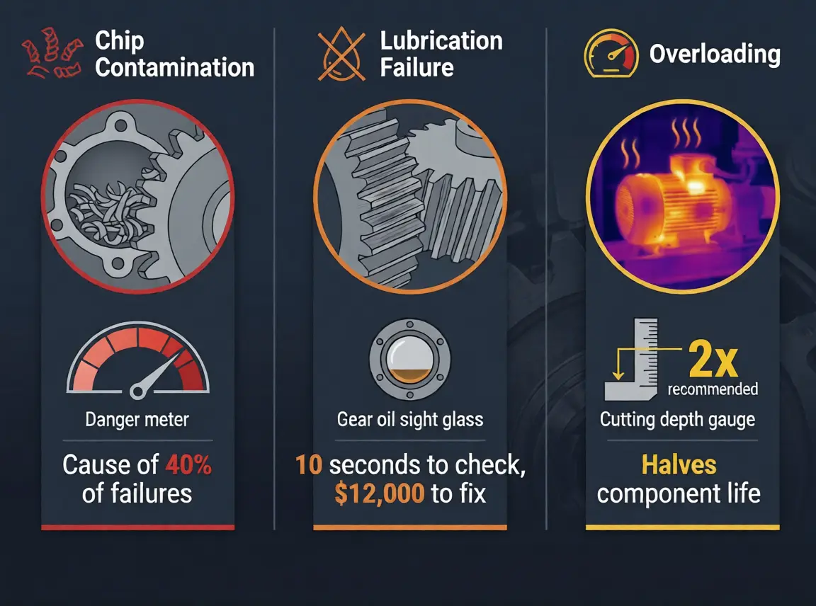
The Three Killers: What Destroys Beveling Machines
In 15+ years of building and servicing beveling machines, I’ve identified three root causes that account for nearly all premature failures. Every maintenance routine should be designed to catch these early.
Killer #1: Chip Contamination
Metal chips from the cutting process are the single biggest threat to your machine. Chips migrate into:
- Gear housings — grinding between gear teeth, accelerating wear
- Bearing surfaces — scoring raceways and causing premature failure
- Mandrel mechanisms — preventing full expansion and causing misalignment
- Feed screws — creating rough spots and inconsistent feed
Prevention: The 3-minute visual inspection and blow-off in the weekly routine. After cutting particularly chip-heavy materials (cast iron, high-carbon steel), blow out the machine after every shift—don’t wait for Friday.
Killer #2: Lubrication Failure
Every moving part in your beveling machine needs a film of lubricant between metal surfaces. Without it, friction increases exponentially, temperatures rise, and surfaces start to micro-weld (galling).
The most common failure mode I see: Gear housing runs dry because nobody checked the level. The gears start running metal-on-metal. By the time anyone notices (usually when the machine starts making noise), the gear teeth are already damaged.
Prevention: The gear oil check in the weekly routine takes literally 10 seconds. Look at the sight glass. If the oil is below the line, add oil. That’s it.
Killer #3: Overloading
Running the machine beyond its rated capacity—too deep a cut, too hard a material, too fast a feed rate—puts stress on every component simultaneously. Motors overheat, gears overload, bearings take shock loads, inserts chip.
The insidious part: Overloading often doesn’t cause immediate failure. It causes accelerated wear that shows up months later as “sudden” failure. The operator who runs 3mm depth of cut instead of the recommended 1.5mm feels like he’s being efficient. He’s actually halving the service life of every component in the machine.
Prevention: Follow the cutting parameter chart that came with your machine. If you’ve lost it, contact us and we’ll send you the correct parameters for your model and material.
Pneumatic Machines: The Maintenance Nobody Does
Pneumatic beveling machines have all the same maintenance needs as electric machines—plus an entire air supply system that most operators completely ignore.
The Air Quality Problem
Compressed air from a standard shop compressor contains:
- Water vapor (condenses inside the motor, causes corrosion)
- Oil mist from the compressor (wrong type of oil contaminates the vane motor)
- Particulates (dirt, rust from the air lines)
What I’ve seen: A customer in the Middle East destroyed three pneumatic motors in one year. Each time they blamed the machine. When I finally visited the site, their air supply had no filter, no dryer, and the air lines were rusty carbon steel with visible water collecting at low points. The vane motor was basically running on a mixture of dirty water and compressor oil.
Pneumatic-Specific Weekly Additions (3 extra minutes)
- Drain the water trap on the FRL unit (Filter-Regulator-Lubricator). If you don’t have an FRL unit, stop reading this article and install one before your next shift
- Check the inline oiler — the oil level should be visible. Refill with ISO VG 10 pneumatic tool oil (NOT motor oil, NOT WD-40, NOT compressor oil)
- Verify inlet pressure — most pneumatic beveling machines need 6-8 bar (85-115 psi) at the machine inlet. Check at the machine, not at the wall. A 30-meter hose run with fittings can drop pressure by 1-2 bar
The FRL Unit: Your Pneumatic Machine’s Life Insurance
If I could give one piece of advice to every pneumatic machine owner, it would be this: install a proper FRL unit within 1 meter of the machine inlet, and maintain it.
| Component | Function | Maintenance |
|---|---|---|
| Filter | Removes particulates and water | Drain bowl weekly. Replace element every 6 months |
| Regulator | Controls pressure to the machine | Set and verify weekly. Replace if it drifts |
| Lubricator | Adds correct oil to the air stream | Check oil level weekly. Refill with ISO VG 10 |
Cost of a quality FRL unit: $80-$150. Cost of replacing a pneumatic motor because you didn’t have one: $1,500-$3,000.
When to Stop Maintaining and Start Replacing
Maintenance extends machine life, but nothing lasts forever. Here’s how I help customers decide when a machine has reached end-of-life.
Replace the component when:
| Component | Replace When | Typical Life (with maintenance) |
|---|---|---|
| Carbide inserts | All edges used | 100-300 bevels per edge (material dependent) |
| Mandrel jaws | Scoring prevents proper grip | 2-4 years |
| Spindle bearings | Detectable play or noise | 3-5 years |
| Gear set | Tooth wear exceeds 0.1mm or backlash is perceptible | 5-8 years |
| Motor (electric) | Brush wear, bearing noise, reduced power | 5-10 years |
| Motor (pneumatic) | Vane wear, reduced speed at rated pressure | 2-4 years |
Replace the machine when:
- Repair cost exceeds 50% of a new machine price
- Multiple major components need replacement simultaneously
- The machine can no longer hold tolerance even after repair
- Parts are no longer available (this happens with discontinued models from other manufacturers—we maintain parts availability for all our current and recent models)
My honest recommendation: A well-maintained beveling machine should last 8-12 years in a production environment. If yours is dying in 2-3 years, the machine isn’t the problem—the maintenance is.
The Real Cost of Skipping Maintenance
Let me put real numbers on this, because “maintenance is important” is advice everyone gives and nobody follows without seeing the math.
Scenario: 8” Schedule 40 carbon steel, 50 bevels per week
| Cost Category | With Weekly Maintenance | Without Maintenance |
|---|---|---|
| Insert cost per year | $800 (normal wear) | $2,400 (premature failure) |
| Unplanned downtime | ~4 hours/year | ~40 hours/year |
| Downtime cost (@$150/hr shop rate) | $600 | $6,000 |
| Major repair (amortized) | $200/year | $2,000/year |
| Maintenance labor (15 min/week) | $400/year | $0 |
| Total annual cost | $2,000 | $10,400 |
The 15-minute weekly routine pays for itself 20x over. And that’s without counting the quality costs—rejected welds, rework, inspector callbacks—that result from a poorly maintained machine producing inconsistent bevels.
The Bottom Line
Beveling machine maintenance isn’t complicated. It’s not time-consuming. It’s not expensive. It’s just not optional.
The 15-minute weekly routine:
- Visual inspection (3 min) — chips, leaks, loose fasteners
- Mandrel/clamping check (3 min) — smooth operation, clean surfaces
- Cutter head and inserts (3 min) — chip check, seating, screw tightness
- Gear oil and lubrication (3 min) — level, color, grease points
- Function test (3 min) — sound, vibration, feed mechanism, temperature
Print this list. Tape it to the machine. Make it part of the weekly routine. The operators who do this consistently are the ones who call me to buy their second machine after 10 years—not the ones who call me for emergency repair quotes after 18 months.
Need maintenance support for your specific machine?
Download our maintenance guide: General Maintenance Guide PDF — Covers all Kedes beveling machine models with detailed procedures and torque specifications.
Order spare parts: Contact our parts department — We maintain full spare parts inventory for all current models. Most orders ship within 48 hours.
Understand your machine better: How Beveling Machines Actually Work — If you understand the mechanics, the maintenance makes intuitive sense.
Choosing your first machine? Best Pipe Beveling Machines in 2026 — We factor maintenance costs and spare parts availability into our recommendations.
Already having problems? Tell us your machine model and symptoms and we’ll diagnose remotely. 80% of issues can be identified from a video call.