The Gap Between Code and Reality
I get a version of this call about once a month: a structural steel fabricator has a batch of column splices or moment connections rejected by the CWI. The welds look fine on the outside. The welders are qualified. The WPS is approved. But the UT results come back with lack-of-fusion defects at the root—and nobody can figure out why.
Nine times out of ten, the problem isn’t the welding. It’s the bevel.
The root face was too thick. Or the bevel angle was 2° shallow. Or the thermal cutting left a hardened layer that the first pass couldn’t fuse into. These aren’t exotic failure modes—they’re the predictable result of treating bevel prep as an afterthought.
Here’s what surprises most fabricators: AWS D1.1 is actually more specific about bevel geometry tolerances than many shops realize. The code doesn’t just say “bevel it.” It gives you exact dimensions, exact tolerances, and exact surface requirements. And when your shop-floor process can’t consistently hit those numbers, you’re building rework into every joint.
This guide covers what D1.1 actually requires, where it’s stricter than you think, and what I see shops getting wrong after 15+ years of supplying plate beveling equipment to structural steel fabricators worldwide.
What AWS D1.1 Actually Requires for Bevels
Let’s start with what the code says—not what people think it says.
AWS D1.1 (Structural Welding Code—Steel) governs welded connections in steel structures: buildings, bridges (D1.5 for bridge-specific requirements), towers, industrial platforms, and everything in between. For bevel prep, the critical sections are:
- Clause 5 — Fabrication: Surface preparation, thermal cutting requirements, dimensional tolerances
- Clause 3 & Annex B — Prequalified WPSs: Joint detail tables with specific bevel angles, root faces, root openings, and tolerances
- Clause 5.23.3 — Weld Profiles & Surface Roughness: What the finished prep surface must look like
The bevel parameters D1.1 controls
| Parameter | What D1.1 specifies | Why it matters |
|---|---|---|
| Bevel angle | Per joint detail (typically 30° or 45° bevel = 60° or 90° included) | Controls weld volume and root access |
| Root face | Per joint detail (0–3mm typical) | Controls root pass penetration |
| Root opening | Per joint detail + tolerance | Controls root pass fusion |
| Surface roughness | 1000 µin (25 µm) max per Clause 5.23.3.1 | Prevents inclusions and fusion defects |
| Gouge/backgouge depth | As needed for sound weld metal per Clause 5.23 | Ensures complete joint penetration |
This isn’t a suggestion list. Every one of these has a dimensional tolerance, and your CWI is measuring them before welding starts.
Prequalified Joint Details — The Part Everyone Skips
Here’s where AWS D1.1 gets specific—and where most fabricators stop reading too early.
Annex B (formerly Figure 3.3 in older editions) contains dozens of prequalified joint details. Each one is a complete geometric specification for a specific joint configuration. If you’re using a prequalified WPS (and most structural shops do, because qualification testing is expensive), you must match these details exactly.
Complete Joint Penetration (CJP) groove welds — the critical ones
CJP groove welds are where bevel prep matters most, because incomplete penetration is a rejectable defect. These joints carry full structural load. Here are the joint configurations you’ll encounter constantly in structural steel:
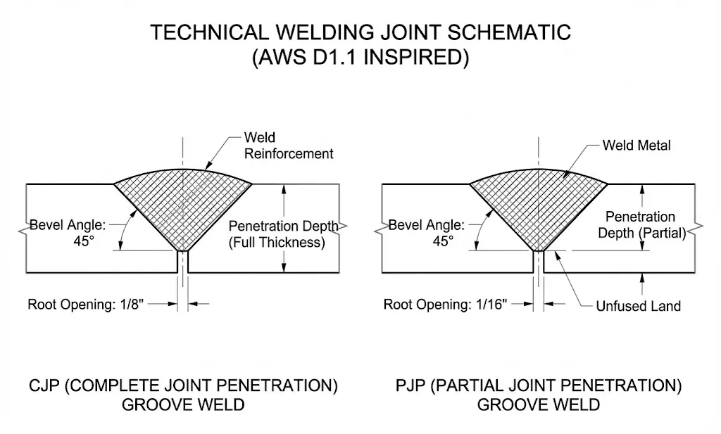 AWS D1.1 prequalified CJP groove joint details. Every dimension has a tolerance—and your bevel prep has to hit all of them simultaneously.
Common CJP joints in structural work
| Joint | Typical application | Bevel angle | Root opening | Root face | Backing |
|---|---|---|---|---|---|
| B-U2a (Single-V) | Column splices, beam splices | 60° included (30° per side) | 6mm (with backing) | 0mm | Steel backing bar |
| B-U3a (Single-V, no backing) | Field joints requiring backgouge | 60° included | 6mm (as fit) | 0mm | Backgouge + weld |
| B-U4a (Single-bevel) | T-joints, corner joints | 45° bevel | 6mm | 0mm | Steel backing |
| TC-U4a (Single-bevel T) | Moment connections (beam flange to column) | 45° bevel | 6mm | 0mm | Steel backing |
| B-U2 (Single-V, no backing) | Thinner plates, both sides accessible | 60° included | 0–3mm | 0–3mm | None—weld both sides |
The one that trips everyone up: TC-U4a. This is the classic moment connection joint—beam flange to column face. It’s a single-bevel groove with backing bar, and it appears on probably 80% of structural steel projects with moment frames. The bevel is on the beam flange, the column face stays square.
Getting this joint wrong means the entire moment connection is compromised. And I see it done wrong constantly.
The Tolerances Most Shops Ignore
Here’s where the gap between “code” and “shop floor” gets expensive.
AWS D1.1 Table 5.4 (Assembly Tolerances) specifies dimensional tolerances for groove welds as fitted. These tolerances apply to the assembled joint—meaning your bevel prep needs to be good enough that after fit-up, the joint still falls within these windows.
D1.1 assembly tolerances for groove welds
| Parameter | With backing bar | Without backing bar |
|---|---|---|
| Root opening (nominal) | +6mm / −2mm | +3mm / −2mm |
| Root face | ±2mm | ±2mm |
| Groove angle | ±5° from nominal | ±5° from nominal |
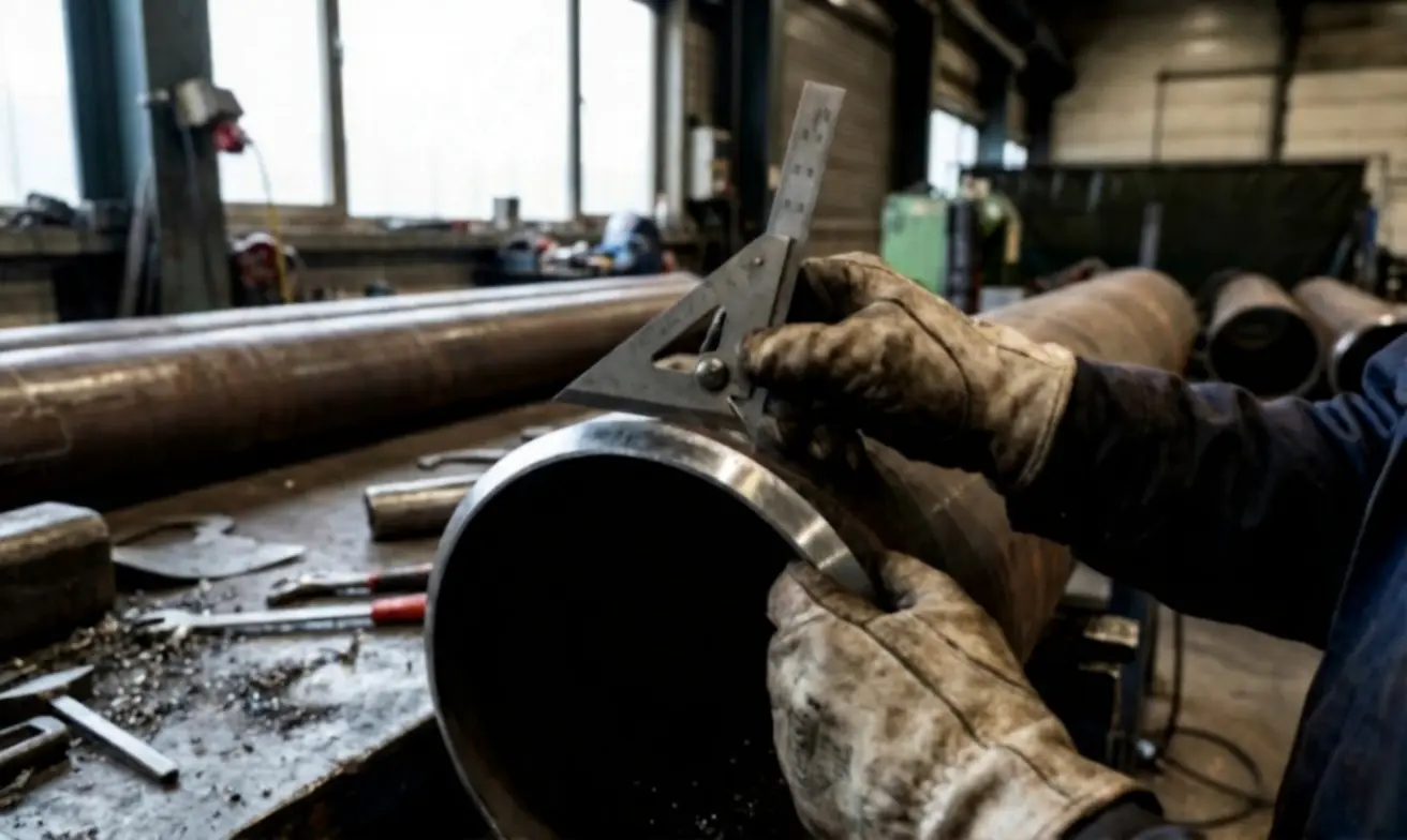 Bevel gauge verification on a CJP groove joint. If you’re not measuring these dimensions before welding, you’re gambling with the UT results.
±5° sounds generous—until you do the math.
A prequalified V-groove calls for 60° included angle (30° per side). At −5° tolerance, you’re at 25° per side = 50° included. That’s getting tight for root access with FCAW-GS, which is the dominant process in structural steel shops. Your welder can probably still get the root pass in, but the risk of lack-of-fusion at the root just went up significantly.
And here’s what people miss: these tolerances stack. If your bevel angle is 2° shallow AND your root face is 1.5mm too thick AND your root opening is 1mm tight, each individual dimension might be within tolerance—but the combined effect on weldability is severe. The welder is fighting geometry on three fronts simultaneously.
What ±2mm root face actually means in practice
On structural plate, “root face” often means the landing at the bottom of the bevel—the narrow flat portion that the root pass has to burn through (or fuse to the backing bar through).
D1.1 joints with backing bars typically call for zero root face—the bevel goes all the way to a knife edge. If your cutting process leaves a 2mm root face that wasn’t in the joint detail, the welder now has to burn through 2mm of steel to reach the backing bar. On a 20mm plate with FCAW at 250A, that’s marginal. On a 40mm plate with a single-bevel joint, it can mean incomplete fusion that won’t show up until UT.
This is the single most common D1.1 bevel defect I see: unintended root face from imprecise cutting. Flame cutting creates it. Poorly set-up machine cutting creates it. Hand grinding to “fix” it creates an inconsistent root face that’s worse than none at all.
Thermal Cutting and the Roughness Trap
AWS D1.1 Clause 5.23.3.1 requires that thermally cut surfaces be cleaned and meet a surface roughness of 1000 µin (25 µm) ANSI/ASME B46.1. This applies to oxy-fuel cut surfaces, plasma cut surfaces, and any other thermal cutting process.
What this means in practice
Most oxy-fuel cut surfaces in a well-run shop will meet the 1000 µin requirement without additional work. Plasma cutting is borderline—high-definition plasma typically passes, but conventional plasma on thick plate often doesn’t.
But here’s the clause most shops don’t read: D1.1 Clause 5.23.3.2 requires that thermally cut surfaces that will be subject to calculated stress must be free of “gouges, notches, and reasonably smooth.” Where roughness exceeds the limit, the surface must be ground smooth.
For CJP groove welds in moment connections, beam splices, and column splices—all of which carry calculated stress—this means:
- Your thermal cut bevel surface must meet 1000 µin
- Any gouges or notches from the cutting process must be removed
- The re-entrant corners at the root must be smooth, not sharp
I’ve seen structural shops fail inspection because the drag lines from oxy-fuel cutting created stress risers at the root of the bevel. The weld was fine. The bevel surface wasn’t.
Why cold mechanical cutting sidesteps this entirely
Mechanical milling—the process used by plate edge milling machines—produces a surface finish of Ra 3.2–6.3 µm (125–250 µin). That’s 4–8x better than the D1.1 requirement, with no thermal effects, no drag lines, and no hardened layer.
There’s no post-cut grinding. No surface roughness inspection drama. No hardness testing questions. The bevel surface comes off the machine ready to weld.
I covered the full thermal vs. mechanical comparison in the cold cutting vs thermal cutting guide—but for D1.1 structural work specifically, the surface roughness clause is where mechanical cutting pays for itself in avoided inspection hassles.
Plate Thickness Drives Everything
In structural steel, plate thickness determines which joint detail you use, which bevel geometry applies, and how critical your bevel prep becomes. Here’s how it breaks down:
Thin plate (≤12mm)
- Typical joints: Square-groove, partial joint penetration where allowed
- Bevel prep: Minimal or none. Square-cut edges with proper root opening are often sufficient
- Where shops get it wrong: Applying full bevels when a fillet weld or PJP groove was specified. Over-beveling thin plates wastes time and weld metal
Medium plate (12–25mm)
- Typical joints: Single-V or single-bevel CJP with backing
- Bevel prep: Standard 30° or 45° bevel, consistent root face critical
- Where shops get it wrong: Inconsistent bevel angles from flame cutting, especially on the 45° single-bevel for T-joints. A 45° bevel is harder to flame-cut consistently than a 30° bevel
Thick plate (25–50mm)
- Typical joints: Single-V or double-V CJP, J-prep for thicker sections
- Bevel prep: This is where weld volume becomes a cost driver. The difference between a 45° and 30° bevel on 40mm plate is significant:
| Bevel angle (per side) | Approximate weld volume (40mm plate, per meter) | Relative cost |
|---|---|---|
| 22.5° (45° included) | ~180 cm³ | 1.0x |
| 30° (60° included) | ~280 cm³ | 1.6x |
| 45° (90° included) | ~640 cm³ | 3.6x |
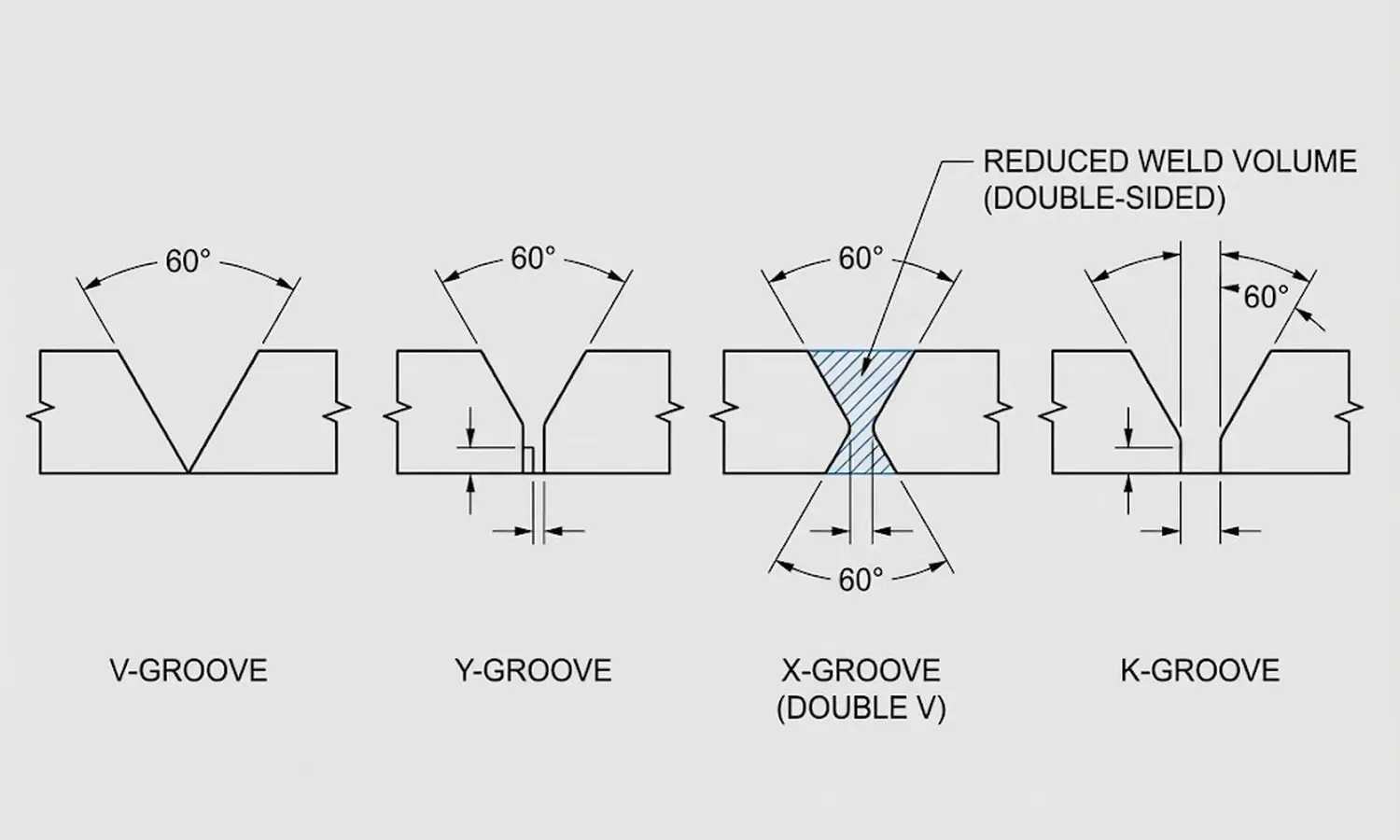 Common plate bevel profiles in structural steel. Thicker plates demand compound or double-sided bevels—getting the geometry right becomes exponentially more important.
On a steel construction project with hundreds of meters of CJP groove welds, the bevel angle directly determines your welding labor and consumable costs. This is why some engineers specify 45° included angle instead of 60° for thick plate—it cuts weld volume nearly in half. But you need your WPS qualified for that angle, and your bevel prep has to hit it precisely.
Very thick plate (50mm+)
- Typical joints: Double-V, double-bevel, or J-prep
- Bevel prep: Almost always machine-cut. The volume of metal to remove makes flame cutting slow and imprecise. Heavy-duty plate milling machines become essential here—no fabricator is hand-grinding a 50mm double-V bevel and hitting D1.1 tolerances consistently
For a deeper dive into bevel angle selection by code, check the pipe bevel angles code requirements guide—many of the angle selection principles apply to plate work too.
Where Shops Actually Fail Inspection
After years of discussing bevel prep failures with CWIs and fabrication QC managers, here are the top five D1.1 bevel-related rejection causes I see, ranked by frequency:
1. Inconsistent root face on CJP joints with backing
The scenario: Shop flame-cuts 45° bevels on beam flanges for moment connections. The root face varies from 0–3mm along the length of the cut. Fit-up looks acceptable, but the backing bar contact is inconsistent—some areas have a gap, others are tight.
The result: Root pass fusion is inconsistent. UT shows intermittent lack-of-fusion at the root. Entire joint requires backgouging and re-welding.
The fix: Machine-cut bevels produce consistent root face within 0.5mm along the entire length. Our GL Series plate milling machines hold this tolerance because the cutter follows a rigid mechanical path—there’s no operator-dependent variation in the root geometry.
2. Bevel angle variation along the joint length
The scenario: A 3-meter beam splice with V-groove. The oxy-fuel cut bevel measures 30° at the start, 27° in the middle, and 32° at the end. All within the ±5° tolerance individually, but the welder has to adjust technique along the length.
The result: Inconsistent weld profile, possible UT indications from the varied root geometry.
The fix: Mechanical beveling maintains constant angle because the cutter head is set to a fixed angle. Whether the plate is 500mm or 3 meters long, the first millimeter and the last millimeter have the same angle.
3. Hardened layer from oxy-fuel or plasma cutting
The scenario: Oxy-fuel cut on A572 Grade 50 plate. The heat-affected zone creates a hardened layer on the bevel face. The first weld pass deposits into hardened base metal.
The result: Possible hydrogen-assisted cracking in the HAZ of the root pass. More likely: lack-of-fusion defects because the arc can’t properly wet the hardened surface.
The fix: Either grind the bevel face to remove the HAZ (adds time and labor), or use mechanical cutting from the start. The DMM feed-through beveling machines produce a clean, cold-cut surface with no thermal effects.
4. Root opening too tight after fit-up
The scenario: Bevel dimensions are correct, but the root opening at assembly is less than specified. The beam flange sits too close to the column face—usually because the bevel wasn’t deep enough to account for the backing bar thickness.
The result: Welder can’t get proper root pass penetration. The backing bar becomes a crevice that traps slag.
The fix: This is a fit-up issue, but it starts with bevel consistency. When every bevel is identical, the fitters can establish a repeatable assembly process. When every bevel is different, each joint becomes a custom fit-up.
5. Gouge marks and notches in the bevel face
The scenario: After flame cutting, the operator uses an angle grinder to clean up the bevel surface. The grinder leaves gouge marks—shallow grooves perpendicular to the welding direction.
The result: Stress risers in the bevel face that can initiate fatigue cracks in cyclically loaded structures. CWI rejects the prep.
The fix: If you’re going to grind, grind in the direction of welding. Or skip the grinding entirely by using a cutting process that doesn’t need cleanup.
Equipment That Meets D1.1 Tolerances
For structural steel shops working under AWS D1.1, the bevel prep equipment choice comes down to volume, plate thickness, and whether you’re doing the work in-shop or in the field.
High-volume shop fabrication: GL Series Plate Edge Milling Machine
The GL Series is what I recommend for structural steel fabricators with steady production volume. It’s a self-traveling plate edge milling machine that runs along the plate edge, cutting a precise bevel in a single pass.
- Capacity: Up to 80mm bevel width (GL-880 dual spindle model)
- Angle range: 15°–60° (covers every D1.1 joint detail)
- Surface finish: Ra 3.2–6.3 µm—far exceeding D1.1’s 1000 µin (25 µm) requirement
- Consistency: Mechanical feed produces identical bevel geometry from start to finish
- Throughput: 0.3–1.5 m/min depending on material and bevel depth
For moment connection work where you’re beveling hundreds of beam flanges per project, this machine turns bevel prep from a bottleneck into a production step. Set the angle, set the depth, start the machine, walk away.
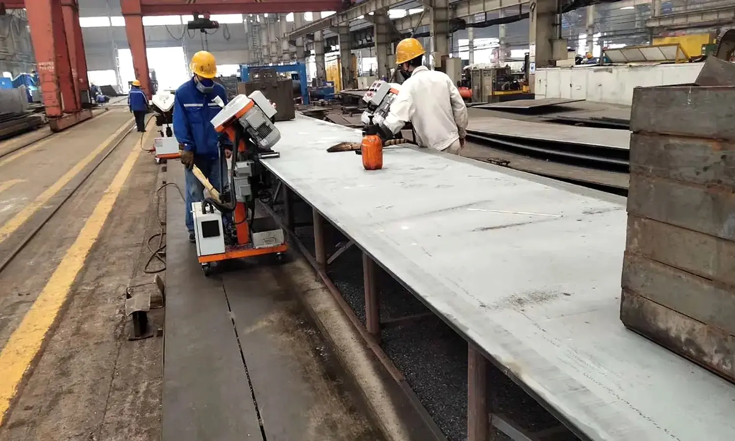 GL Series self-propelled plate beveler in action. The machine travels along the plate edge autonomously—one operator can run multiple machines simultaneously.
Production-line beveling: DMM Series
For fabricators who process plate edges as part of a production flow—think structural plate girders, box columns, or heavy built-up sections—the DMM series offers different configurations for different workflows:
- DMM-20D Feed-Through: Plates pass through continuously. Best for single-edge beveling at high volume
- DMM-90X Flip-Type: 180° flip mechanism bevels both edges without repositioning. Ideal for double-bevel joints
- DMM-1232 Double-Sided: Simultaneous top and bottom beveling. Maximum throughput for double-V preps
On a bridge fabrication project where every girder flange needs double-V beveling at 30° per side, the DMM-1232 cuts total prep time roughly in half compared to single-side machines. That’s not a sales pitch—it’s geometry.
Field and portable work: SKF-15 Handheld Plate Beveler
Not every structural steel bevel happens in a shop. Field splices, erection welds, and repair work demand portable equipment. The SKF-15 handheld plate beveling machine handles field beveling on structural plate where you can’t bring the plate to a stationary machine.
It won’t match the precision or speed of the GL or DMM series, but it’s dramatically better than an angle grinder for field bevel prep—consistent angle, consistent root face, no thermal effects.
What about the existing methods?
Let me be direct about what I see in structural steel shops:
Oxy-fuel cutting with manual track: Works for rough beveling. Requires post-cut grinding on CJP joints. Root face inconsistency is the chronic problem. For PJP groove welds where tolerances are looser, it’s adequate.
Plasma cutting with bevel head: Better than oxy-fuel for thin-to-medium plate. Still produces a HAZ that may need grinding. Angle consistency depends on the CNC program quality.
Angle grinders: Fine for cleanup and minor correction. Not a primary beveling method for any shop that values schedule or weld quality. I’ve written extensively about why grinders cost more than they save.
The Bottom Line
AWS D1.1 beveling requirements aren’t complicated—they’re specific. The code tells you exactly what angle, what root face, what root opening, and what surface finish you need. The problem is that most shops use cutting processes that can’t consistently hit those specs, then spend time and money on grinding, rework, and re-inspection.
Here’s my decision framework for D1.1 structural steel bevel prep:
- High-volume shop work (beam flanges, column splices): GL Series plate edge milling — consistent, fast, exceeds D1.1 surface requirements
- Production-line plate prep (girders, box columns): DMM Series — choose the configuration that matches your workflow
- Thick plate double-V joints: DMM-900X dual-spindle or DMM-1232 double-sided — handles the geometry that manual methods can’t
- Field splices and erection welds: SKF-15 handheld plate beveler — portable precision that beats a grinder every time
If you’re running a structural steel shop and want to evaluate whether machine beveling makes sense for your volume, send me:
- Typical plate grades (A36, A572 Gr 50, A992, etc.)
- Thickness range you commonly bevel
- Joint types (single-V, single-bevel, double-V)
- Monthly volume in meters of bevel
- Current process (oxy-fuel, plasma, grinder)
I’ll tell you straight whether the investment makes sense for your shop—or if your current process is genuinely sufficient for your volume and quality requirements.
Related reading:
- Pipe Bevel Angles & Code Requirements — Angle specs across ASME, AWS, and API codes
- ASME B31.3 Beveling Requirements — How process piping code compares to D1.1
- Cold Cutting vs Thermal Cutting — The metallurgical case for mechanical beveling
- Plate Beveling & Edge Milling Guide — Complete overview of plate bevel prep methods
- Steel Construction Beveling Solutions — Our approach to structural steel fabrication
Based on AWS D1.1/D1.1M:2020 (Structural Welding Code—Steel) and field experience with structural steel fabricators across North America, Europe, and Asia. Tolerance data from code tables; rejection rate observations from customer-reported QC data. Always verify requirements against the current edition of D1.1 and your project-specific WPS.