The Disconnect Between Code and Shop Floor
Here’s something that frustrates me: a fabrication shop buys a $200,000 automated welding system, hires certified welders, invests in RT/UT inspection—then bevels their pipe ends with an angle grinder.
And when the radiography comes back with slag inclusions and lack-of-fusion defects, everyone blames the welder.
The welder isn’t the problem. The bevel is.
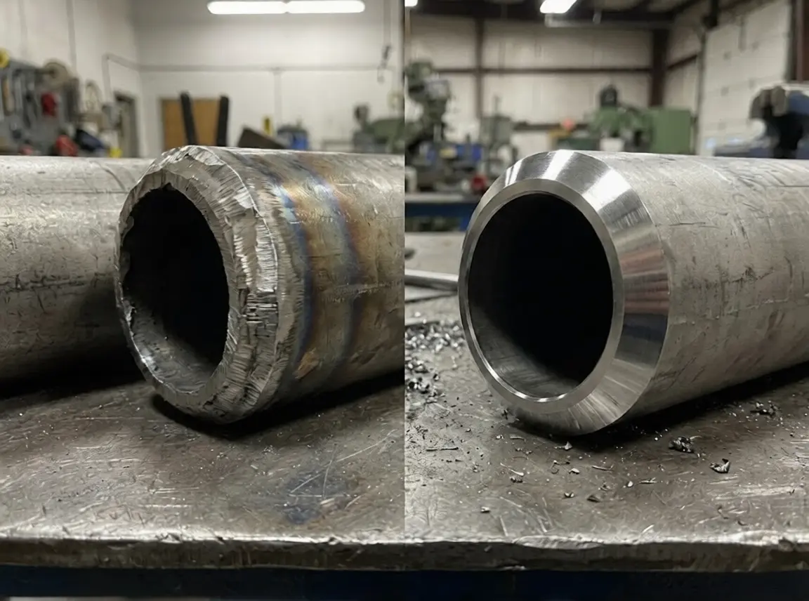 Angle grinder (left) vs. machine bevel (right) — the surface quality difference directly impacts weld integrity under ASME B31.3
ASME B31.3 (Process Piping) is one of the most widely referenced piping codes in the petrochemical, pharmaceutical, and chemical industries. But most shops treat its beveling requirements as an afterthought—“just cut a 37.5° bevel and go.”
That’s not what the code says. And it’s definitely not what the inspector is looking for.
And meeting it consistently comes down to equipment, not effort—it’s exactly why we build purpose-built pipe beveling machines for code-grade edge prep instead of trusting an angle grinder.
Related: If you’re new to pipe beveling fundamentals, start with our Complete Guide to Pipe Beveling before diving into B31.3 specifics. For a full breakdown of bevel angle requirements across all major codes, see our companion article.
What ASME B31.3 Actually Requires for Bevel Preparation
Let me be direct: ASME B31.3 itself does not specify a single bevel angle. This surprises people.
What B31.3 does is:
- Defer to ASME B16.25 for standard weld end preparation geometry
- Require that the bevel match the qualified WPS (Welding Procedure Specification)
- Mandate specific tolerances for fit-up, alignment, and surface condition
- Restrict certain cutting processes for specific materials (Chapter IX, Section 328.4)
The code’s logic is simple: the bevel geometry must produce a sound weld as proven by your WPS qualification. If your WPS was qualified with a 37.5° bevel angle, ±2.5° root face of 1.6mm, and a 1.6mm root gap—those are your requirements. Not some generic “industry standard.”
My blunt advice: If you cannot tell me the exact bevel parameters from your WPS within 10 seconds, you have a documentation problem that will become an inspection problem. For a comparison of how different codes (AWS D1.1, ASME B31.1, EN 13480) handle bevel specifications, see our Pipe Bevel Angles & Code Requirements guide.
Weld End Preparation per ASME B16.25
ASME B16.25 is the companion standard that B31.3 references for butt-welding end geometry. Here’s what most shops get wrong:
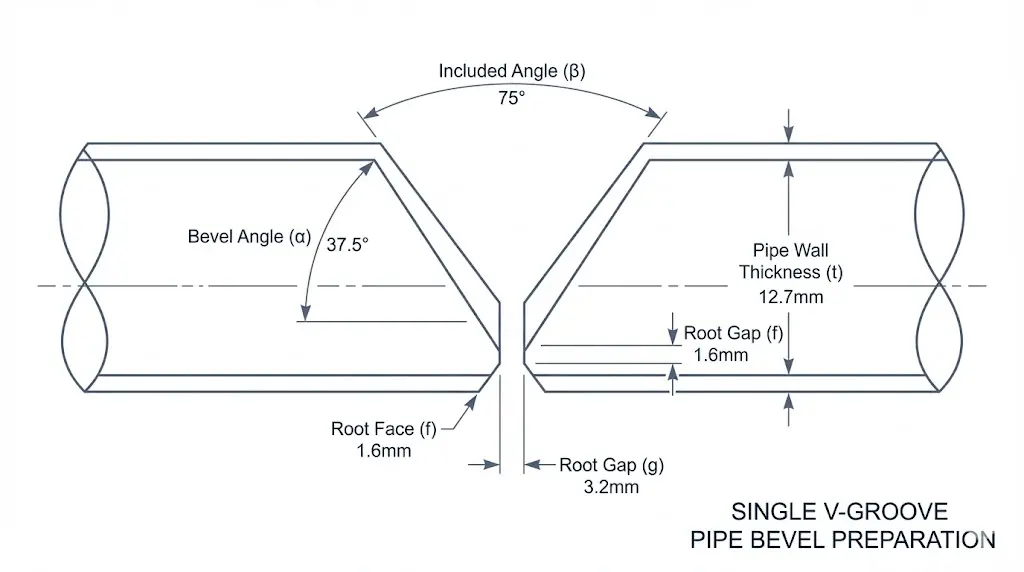 Key bevel dimensions per ASME B16.25: bevel angle, root face, and root gap must all match your WPS
Standard Bevel (Wall ≤ 22mm / 0.875”)
| Parameter | B16.25 Requirement |
|---|---|
| Bevel Angle | 37.5° ± 2.5° |
| Root Face | 1.6mm ± 0.8mm (1/16” ± 1/32”) |
| Root Opening | Per WPS (typically 1.6mm / 1/16”) |
This is straightforward. A basic V-bevel. Most portable beveling machines handle this easily.
Compound Bevel (Wall > 22mm / 0.875”)
| Parameter | B16.25 Requirement |
|---|---|
| Primary Angle | 37.5° ± 2.5° (to ~5mm depth from root) |
| Secondary Angle | 10° ± 5° (remainder of wall) |
| Root Face | 1.6mm ± 0.8mm |
This is where shops lose money. Many fabricators still cut a full 37.5° V-groove on 30mm+ wall pipe because their equipment can’t do compound bevels. The result? Double the filler metal, double the passes, double the labor. A heavy-duty beveling machine like the ISE-II Series solves this with built-in compound bevel capability.
J-Prep (Heavy Wall, Special Applications)
B16.25 also allows J-prep geometry, though it requires agreement between parties. For heavy wall piping (>25mm) in B31.3 service, J-prep can reduce weld volume by 30–50%.
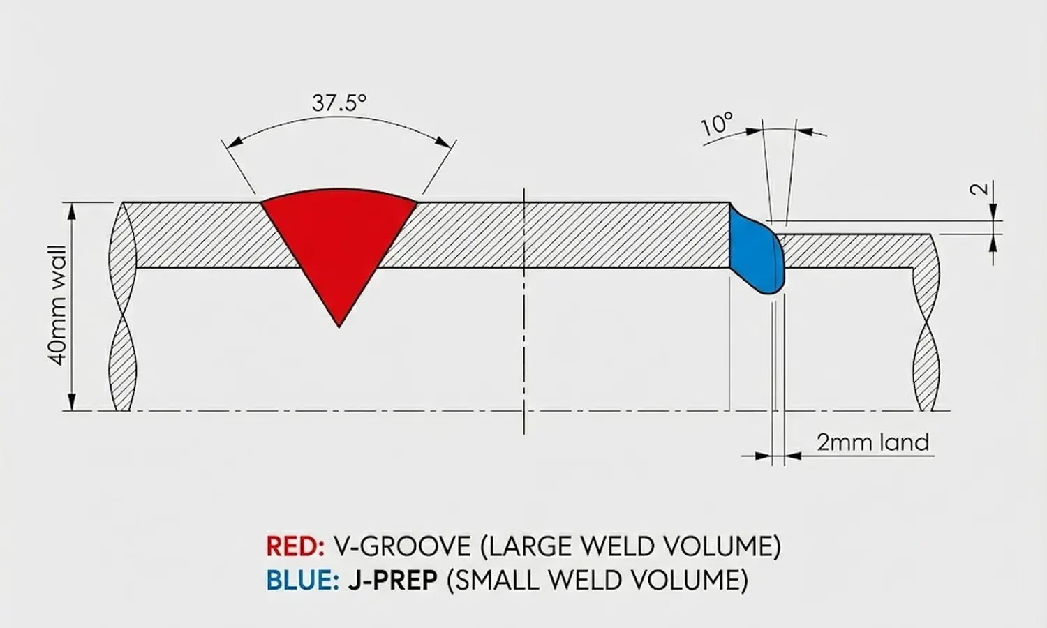 V-groove (left) vs. J-prep (right) — the shaded area represents weld fill volume. J-prep saves 30–50% on filler metal and labor. See our Bevel Types Complete Guide for detailed geometry specifications.
My experience: I’ve seen refineries save $15,000+ per shutdown turnaround just by switching from V-groove to J-prep on their thick-wall chrome-moly piping. The code allows it—your WPS just needs to be qualified for it.
Surface Finish and HAZ: The Requirements Nobody Reads
Section 328.4 of ASME B31.3 states that weld end preparation must produce a surface suitable for the specified welding process. Sounds vague? It’s not.
In practice, this means:
Surface Roughness
- Machine-cut or ground surfaces must be free of deep scratches, gouges, and tear marks
- Oxide scale from thermal cutting must be removed
- The surface should be metallurgically clean—no carburized or nitrided layers
Heat Affected Zone (HAZ)
Here’s the trap that catches shops working with P91/P22, stainless steel, duplex, and nickel alloys:
ASME B31.3 Section 328.4.2: “Thermally cut surfaces shall be prepared for welding by mechanical means such as grinding, machining, or chipping.”
Translation: If you torch-cut or plasma-cut these materials, you MUST mechanically remove the HAZ before welding.
I’ve watched shops spend 2–3 hours per joint grinding out HAZ on P91 pipe. That’s 2–3 hours of labor that wouldn’t exist if they had used a cold-cutting beveling machine in the first place.
| Method | HAZ? | Post-Cut Grinding? | B31.3 Compliant? |
|---|---|---|---|
| Oxy-fuel cutting | Yes (deep) | Mandatory | Only after grinding |
| Plasma cutting | Yes (moderate) | Mandatory | Only after grinding |
| Cold cutting (milling) | No | Not required | Immediately compliant |
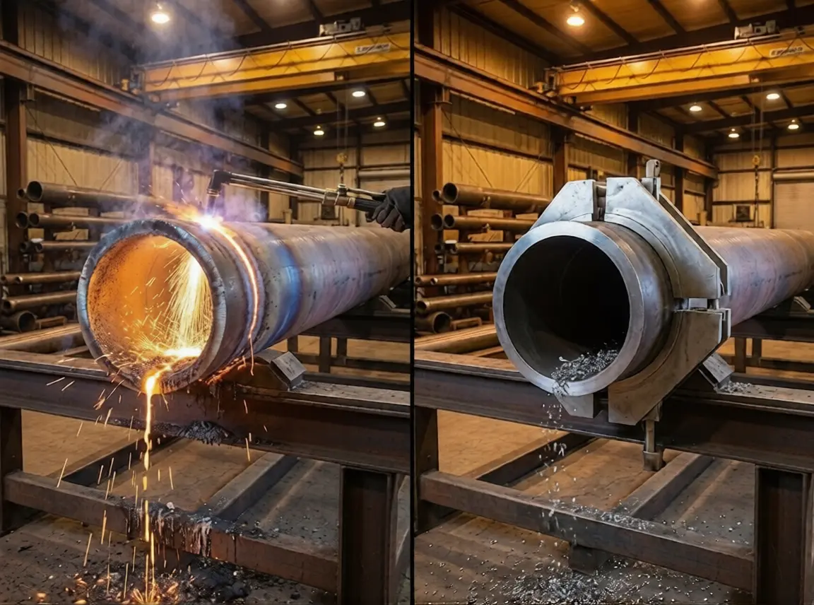 Thermal cut (top) shows visible HAZ discoloration that must be ground away. Cold cut (bottom) produces a clean, metallurgically unaffected surface ready for welding.
My stance: For any B31.3 process piping in Category M (high-hazard fluid service) or involving chrome-moly/stainless materials, cold cutting isn’t optional—it’s the only approach that makes economic sense.
Alignment and Fit-Up: Where B31.3 Gets Specific
This is where ASME B31.3 gets very prescriptive, and where I see the most inspection failures.
Internal Misalignment (Hi-Lo)
Per ASME B31.3 Section 328.4.3, internal misalignment must be minimized. The acceptance criteria comes from your WPS and the applicable examination standard, but the practical limits are:
| Pipe Wall Thickness | Maximum Hi-Lo (Typical) |
|---|---|
| ≤ 6mm | 1.0mm |
| 6–19mm | 1.6mm |
| > 19mm | Per engineering design |
The real-world problem: Seamless pipes (especially in larger diameters) routinely have wall thickness variations of 12.5% per ASTM tolerances. Two pipes that are “the same schedule” can have 2–3mm of ID mismatch.
 Proper root face and root gap dimensions are critical for B31.3 fit-up acceptance. Inconsistent bevels make achieving these tolerances nearly impossible.
The solution is counterboring. Using an ID-mounted machine, you machine the pipe bore to a consistent diameter, creating a smooth internal transition. B31.3 allows this—and on critical piping (Category M, lethal service), inspectors will often require it.
→ Our ISC Block Type machines handle counterboring and beveling in a single setup
Material-Specific Traps in B31.3
P91 / P22 (Chrome-Moly Steels)
ASME B31.3 requires preheat for cutting these materials, even for mechanical cutting if the ambient temperature is below 10°C. But the bigger trap is hardness.
After thermal cutting, the HAZ on P91 can exceed 400 HV—well above the 248 HV maximum typically specified. This means:
- Torch cut → HAZ forms → Hardness too high → Must grind 3mm+ deep → Re-test hardness
- Cold cut → No HAZ → Hardness unchanged → Weld immediately
I refuse to recommend thermal cutting for P91 piping. The rework cost alone exceeds the price of a proper cold-cutting machine.
Duplex & Super Duplex Stainless Steel
B31.3 doesn’t call this out explicitly, but the metallurgy demands it: thermal cutting disrupts the ferrite-austenite balance in the HAZ, potentially causing sigma phase formation. Most project specs for duplex piping explicitly require cold cutting.
Low-Temperature Carbon Steel (LTCS)
For piping in cryogenic or low-temperature service, B31.3 requires impact testing. Any HAZ from thermal cutting must be verified not to degrade impact properties—another reason cold cutting eliminates an entire category of risk.
Choosing the right machine? Material type, wall thickness, and site conditions all factor into the decision. See our Best Pipe Beveling Machines Guide and Portable vs Stationary Beveling Machine comparison.
The Thermal Cutting Pitfall: A Cost Nobody Calculates
Let me show you what “just use a torch” actually costs on a B31.3 project:
| Cost Element | Thermal Cut + Grind | Cold Cut (Machine Bevel) |
|---|---|---|
| Cutting time | 15 min | 20 min |
| Grinding HAZ | 120 min | 0 min |
| Hardness testing (P91) | 30 min + equipment | Not required |
| Surface prep | 45 min | 0 min |
| Total prep time per joint | 3.5 hours | 20 minutes |
| Bevel accuracy | ±5° (hand-dependent) | ±0.5° (machine-controlled) |
| Rework probability | 15–25% | < 2% |
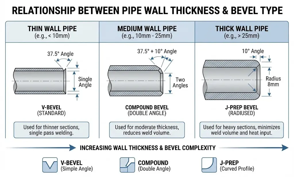 Bevel type selection by wall thickness: standard V for ≤22mm, compound bevel for >22mm, J-prep for heavy wall >25mm
The cutting step itself is faster with a torch. Everything after it is slower. And on a B31.3 project with 500+ joints, that 3-hour difference per joint isn’t trivial—it’s the difference between finishing on schedule and paying penalty costs.
B31.3 Minimum Distance Between Welds
A frequently asked question is: what is the minimum distance between two circumferential welds under ASME B31.3?
B31.3 Section 328.4.3 does not specify a single fixed distance. Instead, the rule is based on avoiding overlap of heat-affected zones from adjacent welds. The practical guidelines:
| Wall Thickness | Minimum Weld Spacing | Rationale |
|---|---|---|
| ≤ 19mm (3/4”) | 4× nominal wall thickness, minimum 25mm (1”) | Prevent HAZ overlap |
| > 19mm (3/4”) | Greater of 4× wall thickness or as-welded width + 25mm | Allow adequate NDE coverage |
| Any (branch connections) | The weld-to-weld distance must allow proper NDE access | Inspection geometry constraints |
Why this matters for beveling: When welds are closely spaced, the bevel on the second joint must not encroach on the HAZ of the first weld. This requires precise bevel length control — another reason to use machine beveling rather than angle grinders, which cannot control the bevel endpoint accurately.
Common mistake: Fabricators cut a short spool piece and end up with two welds too close together. The inspector rejects it not because the welds are bad, but because NDE coverage is impossible. Always check your WPS and the engineering drawing for minimum weld spacing requirements before cutting.
Real Case: 28 Failed Radiographs on a Pharma Project
A pharmaceutical plant contractor was building a Category M piping system (316L stainless, 8” Sch 40). They were using plasma cutting for bevel preparation and manual grinding for cleanup.
Out of 180 joints, 28 failed radiographic examination. The primary defect? Lack of fusion at the root.
When I examined their bevels, the problem was obvious:
- Inconsistent bevel angle (varied from 30° to 42° across the circumference)
- Uneven root face (ground by hand, ranged from 0.5mm to 3mm)
- Residual oxide layer in spots where grinding was insufficient
We provided them with ISE-T Series machines for the remaining work.
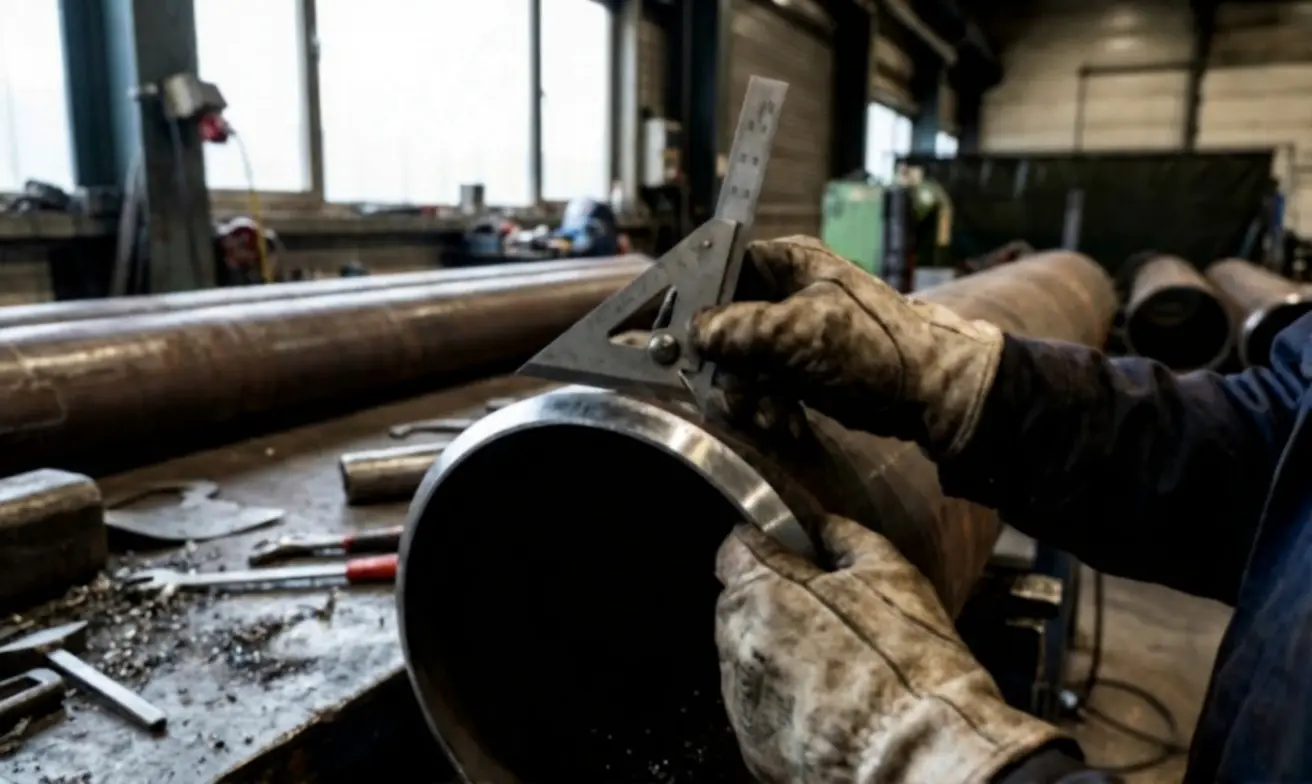 Bevel gauge verification on site — consistent machine-cut bevels pass inspection the first time
The result:
| Metric | Before (Plasma + Grind) | After (Machine Bevel) |
|---|---|---|
| RT reject rate | 15.5% | 1.2% |
| Bevel prep time/joint | 2.5 hours | 18 minutes |
| Root face consistency | ±1.5mm | ±0.3mm |
| Angle consistency | ±6° | ±0.5° |
The rework cost from those 28 failed joints was more than the entire beveling machine investment. That’s the math nobody does before a project starts—but everyone regrets after.
Equipment Selection for B31.3 Compliance
Based on years of supporting B31.3 projects, here’s my straightforward recommendation:
Standard Process Piping (Carbon Steel, ≤ 20mm Wall)
A lightweight, portable beveling machine with accurate angle control is sufficient. The key is repeatability—every bevel must match the WPS.
→ ISE-T Series — Fast setup, consistent angles, handles 2”–24” pipe
Heavy Wall / Chrome-Moly / Critical Service
You need a heavy-duty machine capable of compound bevels and J-prep. Rigidity matters—any vibration on thick-wall P91 means tool chatter and poor surface finish.
→ ISE-II Series — Built for heavy wall, supports J-prep tooling, up to 75mm wall
Hi-Lo / Counterboring Requirements
If you’re working with seamless pipe in Category M or lethal service, counterboring capability is essential. Don’t wait until the inspector flags your Hi-Lo.
→ ISC Block Type — Bevel + counterbore in one setup, internal clamping
Large Diameter Field Work
Split frames for OD-mount applications where ID access is limited.
→ Split Frame Series — 6”–72” range, field-portable, compound bevel capable
Stop Treating Bevel Prep as an Afterthought
ASME B31.3 compliance starts at the bevel—not at the weld. If your bevel geometry doesn’t match your WPS, your surface finish isn’t clean, or your Hi-Lo exceeds tolerance, no amount of welding skill will save you.
The code is clear. The math is clear. The only question is whether you calculate the cost of compliance before the project starts, or after the rework bills arrive.
Need Help Matching Your B31.3 WPS to the Right Equipment?
Send me:
- Pipe diameter, wall thickness, and material grade
- Your WPS bevel requirements (or I can advise)
- Service category (Normal, Category D, Category M)
I’ll recommend the exact machine setup for your project—no guesswork.
→ Browse All Pipe Beveling Machines → Pipe Bevel Angles & Code Requirements (Related Reading) → Bevel Types Complete Guide (Related Reading) → Plate Beveling & Edge Milling Guide (Related Reading)