The Question Behind the Question
“What bevel angle should I use?”
I get this question weekly. And my answer usually annoys people:
“What does your WPS say?”
“I don’t know. Just tell me the standard angle.”
There is no “standard angle.” Cutting a 37.5° bevel because “that’s what everyone uses” is how you end up reworking joints or failing inspections.
Understanding code requirements is only half the equation—choosing the right equipment from a reliable pipe beveling machine manufacturer is equally critical for achieving consistent, code-compliant bevels on every joint.
Bevel Angle vs Included Angle: The Confusion That Costs Money
Before we go further, let’s clear this up—because I’ve seen $50,000 projects delayed over this simple misunderstanding.
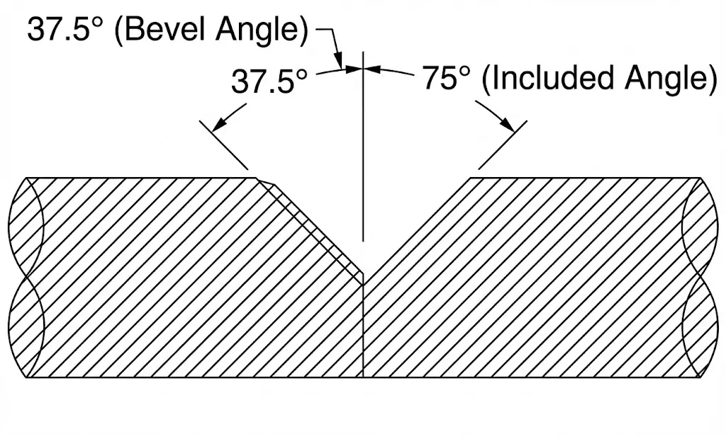 Left: Bevel angle (single side, e.g. 37.5°). Right: Included angle (both sides combined, e.g. 75°)
| Term | Definition | Example |
|---|---|---|
| Bevel Angle | Angle on ONE side of the pipe | 37.5° |
| Included Angle | Total angle when two bevels meet | 75° (= 37.5° × 2) |
The trap: A drawing says “75° groove.” You cut 75° on each side. Now your included angle is 150°. Inspector fails you.
The fix: Always clarify with the drawing owner: “Is this bevel angle or included angle?”
Why There Is No ‘Standard’ Angle
37.5° is common, not universal.
Different factors require different angles:
| Factor | Impact on Bevel Angle |
|---|---|
| Welding code (ASME, AWS, API) | Sets acceptable ranges |
| Welding process (GTAW, SMAW, FCAW) | Affects access requirements |
| Wall thickness | Thicker walls may need compound bevels |
| Joint type | Single-V, double-V, J-prep all differ |
| Filler metal | Some electrodes need wider access |
| Position (horizontal, vertical, overhead) | May require angle adjustment |
The bevel angle in your finished joint must match what was qualified in your WPS. Not what someone told you. Not what you used on the last job. That’s why professional pipe beveling machines with adjustable angle settings are essential—they let you dial in the exact angle your WPS requires.
Don’t know what bevel type to use? Read our guide: Pipe Bevel Types Guide
Code Requirements (Detailed)
Quick Reference Table
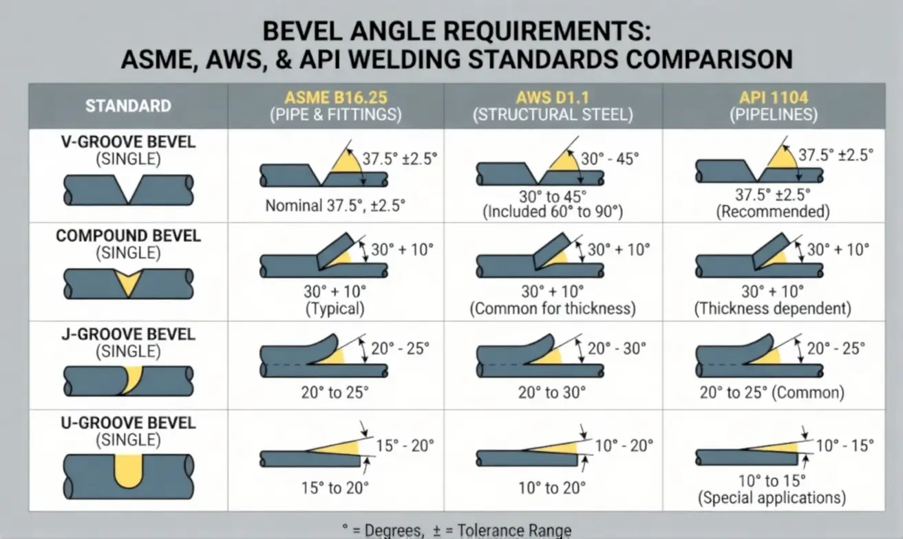 Common bevel angle requirements by welding code
| Code | Standard Angle | Tolerance | Root Face | Notes |
|---|---|---|---|---|
| ASME B31.3 | Per WPS | Per WPS | Per WPS | References qualified procedures |
| ASME IX | Per PQR | ± 5° max | 0-3mm typical | Beyond limits requires requalification |
| AWS D1.1 | 45° (CJP) | ± 5° | 0-3mm | Prequalified joints |
| AWS D1.1 | 30° min | ± 5° | - | Some PJP applications |
| API 1104 | 30° ± 5° | ± 5° | 1.6mm ± 0.8mm | Pipeline work |
| API 1104 | 37.5° ± 2.5° | ± 2.5° | 1.6mm ± 0.8mm | Facility piping |
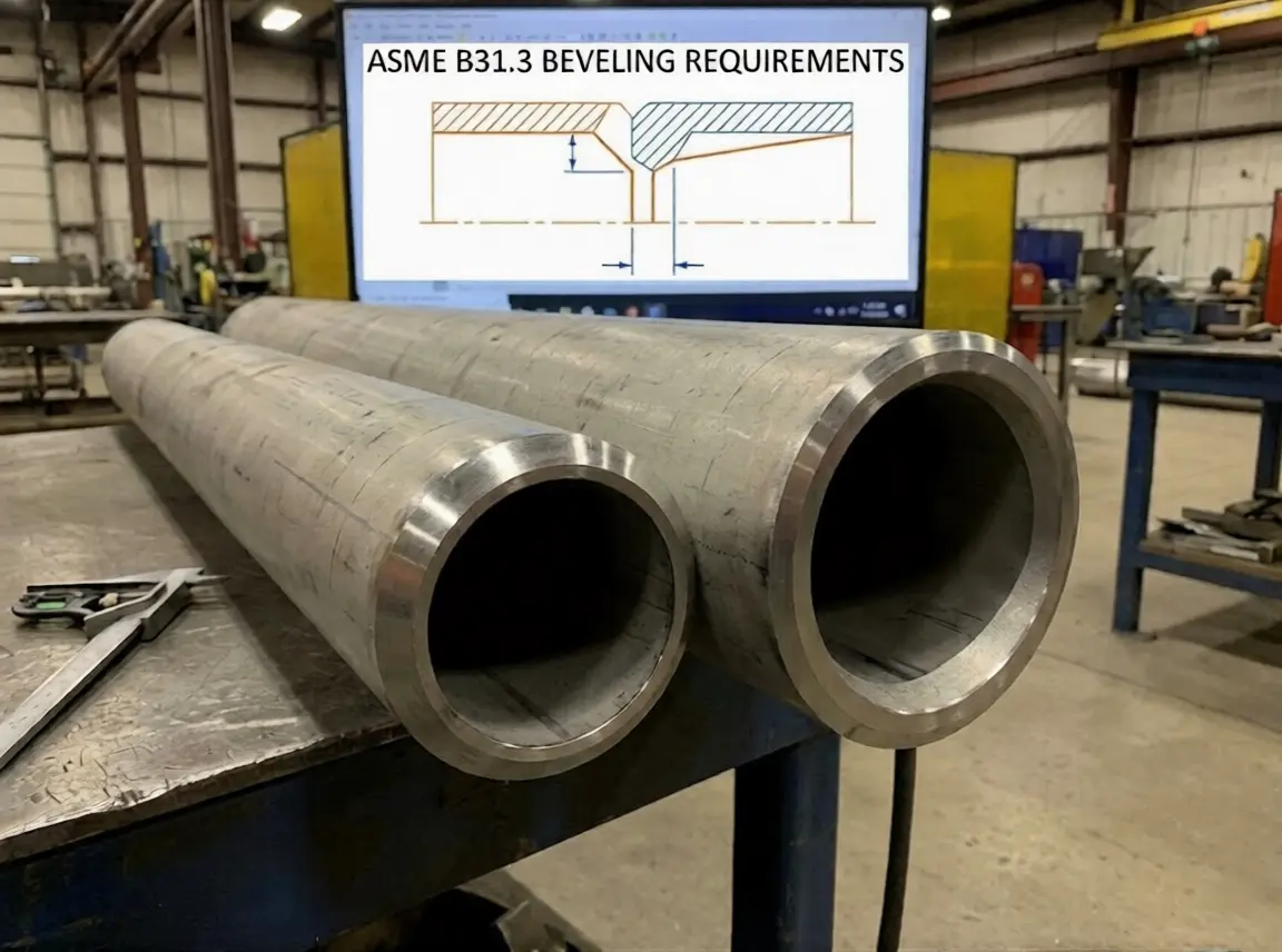
ASME B31.3 (Process Piping)
Doesn’t specify exact angles—refers to qualified welding procedures. Common preparations:
- Standard wall (<15mm): 37.5° ± 2.5° single-V
- Heavy wall (>15mm): Compound bevel or J-prep — see J-bevel angles and dimensions for the full geometry set
- Root face: Typically 1.5mm ± 0.5mm
ASME Section IX
Defines essential variables for procedure qualification. Critical point: Bevel angle changes beyond certain limits require requalification.
| Variable | Limit Before Requalification |
|---|---|
| Groove angle decrease | >5° |
| Root opening decrease | Any decrease |
| Root face increase | >1.5mm |
AWS D1.1 (Structural Welding)
Provides prequalified joint details—meaning you can use them without separate procedure qualification:
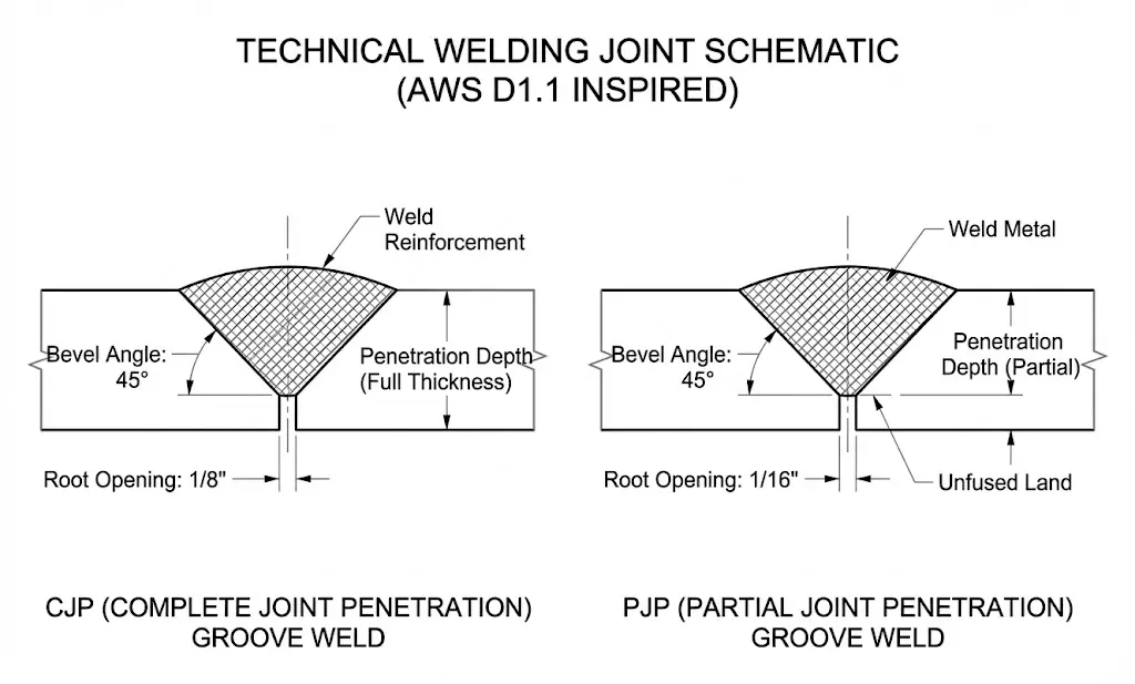 AWS D1.1 prequalified CJP groove weld joint details with bevel angle, root face, and root opening tolerances
- CJP (Complete Joint Penetration): 45° typical, 60° included
- PJP (Partial Joint Penetration): 30° minimum
- Specific tolerances per joint type (see AWS D1.1 Table 3.4)
API 1104 (Pipeline Welding)
More specific than ASME—designed for cross-country pipeline construction:
| Application | Bevel Angle | Root Face | Root Gap |
|---|---|---|---|
| Mainline pipe | 30° ± 5° | 1.6mm ± 0.8mm | 1.6mm ± 0.8mm |
| Tie-ins, facility | 37.5° ± 2.5° | 1.6mm ± 0.8mm | 1.6mm ± 0.8mm |
The Real Answer
Check your project specification first. It should reference the applicable code AND the qualified WPS.
Angle Selection by Application
Not sure what angle your application needs? Here’s what I typically recommend:
By Industry
| Industry | Typical Angle | Why |
|---|---|---|
| Oil & Gas pipelines | 30° | API 1104 standard, minimal filler |
| Process piping | 37.5° | ASME B31.3 common practice |
| Pressure vessels | 37.5° or J-prep | ASME VIII, depends on thickness |
| Structural steel | 45° | AWS D1.1 prequalified |
| Power piping | 37.5° | ASME B31.1 common practice |
| Pharmaceutical/sanitary | 37.5° | Full penetration, clean root |
By Wall Thickness
| Wall Thickness | Recommended Approach |
|---|---|
| ≤6mm | Single bevel, 30-37.5° |
| 6-15mm | V-groove, 37.5° |
| 15-40mm | Consider J-prep to save filler |
| >40mm | Compound bevel or K-groove required |
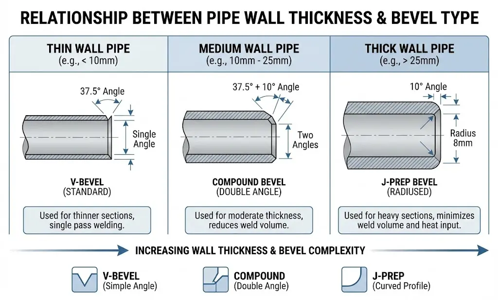 Recommended bevel approach by wall thickness
Three Mistakes That Cause Rework
❌ Mistake 1: Ignoring the WPS
“We always use 37.5°.”
But your WPS for this project was qualified at 30°. Now you have bevels that don’t match the qualified procedure. The inspector fails your joints.
I’ve seen this happen: A fabrication shop lost a $200,000 contract because they cut 37.5° bevels on a pipeline job that specified 30° per API 1104. Every joint had to be reworked.
❌ Mistake 2: Confusing Included Angle vs Bevel Angle
Already covered above—but it’s so common I’ll repeat it:
- Bevel angle: ONE side (e.g., 37.5°)
- Included angle: BOTH sides combined (e.g., 75°)
Misreading this gives you bevels that are double or half what you need.
❌ Mistake 3: Cutting Without Checking Tolerances
Every code allows tolerances—typically ± 2.5° to ± 5°. But tolerances work BOTH ways.
If your WPS says 37.5° ± 2.5°, your acceptable range is 35° to 40°. Cut 34°? Fail. Cut 41°? Fail.
Root Face Matters Too
Bevel angle is only part of the geometry. Root face (land) matters equally—and it’s where most quality problems start.
 Root face (land) and root gap dimensions per ASME B16.25 and API 1104
| Root Face Issue | Welding Problem | Result |
|---|---|---|
| Too thick (>3mm) | Incomplete root penetration | Failed RT/UT inspection |
| Too thin (<1mm) | Burn-through, melt-through | Repair required |
| Uneven around circumference | Inconsistent penetration | Quality defects |
Typical Root Face Requirements
| Application | Root Face | Tolerance |
|---|---|---|
| GTAW root pass | 1.5mm | ± 0.5mm |
| SMAW root pass | 1.5-2.0mm | ± 0.8mm |
| API 1104 | 1.6mm | ± 0.8mm |
My recommendation: If you’re doing critical work (pressure vessels, nuclear, subsea), aim for the middle of the tolerance range. Don’t push the limits.
Pipe Bevel Angle Formula (Width, Face Length, Gauge Check)
People keep searching for a “37.5 degree pipe bevel formula” — so here it is, with the part most references skip: how to use it backwards to verify a cut.
The Formula
The bevel angle, wall thickness and root face are connected by basic trigonometry:
Bevel width  W = (T − RF) × tan(α)
Face length  L = (T − RF) ÷ cos(α)
Check angle  α = arctan( W ÷ (T − RF) )
Where T = wall thickness, RF = root face (land), α = bevel angle, W = the horizontal width of the bevel you can measure with calipers, L = the machined slope face length.
Worked Example: 37.5° on 20 mm Wall
- T = 20 mm, RF = 1.6 mm → effective depth = 18.4 mm
- Bevel width: W = 18.4 × tan 37.5° = 18.4 × 0.767 ≈ 14.1 mm
- Face length: L = 18.4 ÷ cos 37.5° = 18.4 ÷ 0.793 ≈ 23.2 mm
If your measured width is 14 mm-ish, your angle is right. If you measure 10.6 mm, you cut 30°, not 37.5° — catch it before the fit-up crew does.
Quick Multiplier Table
| Bevel Angle | tan(α) — multiply (T − RF) by | Example on 18.4 mm depth |
|---|---|---|
| 30° | 0.577 | 10.6 mm width |
| 37.5° | 0.767 | 14.1 mm width |
| 45° | 1.000 | 18.4 mm width |
One caveat: these formulas describe a straight V-bevel. A J-bevel has a root radius, so its geometry doesn’t reduce to a single tangent — that’s a different dimension set entirely.
How to Check the Angle with a Bevel Gauge
The formula is your backup. The primary tool is a pipe bevel gauge (or a digital angle finder):
- Clean the face — chips and burrs throw the reading off by degrees
- Seat the gauge base on the pipe end face, not the OD — an out-of-square face corrupts the reference plane
- Read at four clock positions (12, 3, 6, 9) — a machine that’s lost rigidity cuts an angle that wanders around the circumference
- Verify the root face with calipers separately — the gauge only tells you the angle
A $30 bevel gauge plus the caliper-and-formula cross-check above catches nearly every out-of-tolerance bevel before welding. Compare that to the cost of one repair cut on a code joint.
Getting It Right
Before Cutting
- Get the WPS—if it doesn’t exist, get one created and qualified
- Read the drawing—confirm bevel angle AND root face
- Clarify terminology—included angle or bevel angle?
- Check tolerances—most codes allow ± 2.5° to ± 5°
- Verify material—different materials may require different preparation
In Production
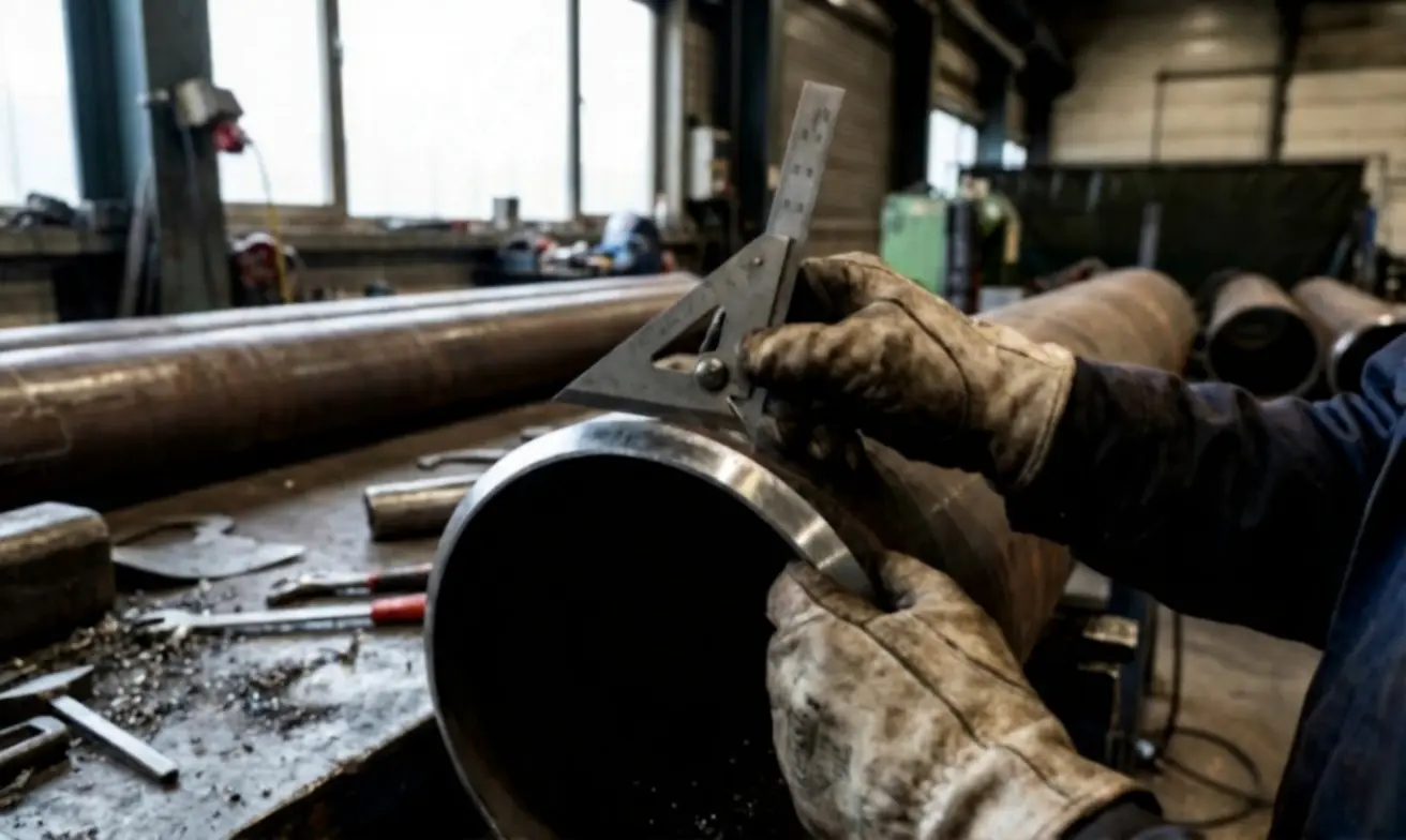 Verifying bevel angle with a gauge on a test cut
- Set machine to specified angle
- Make test cuts on scrap material first
- Verify with a bevel gauge—don’t trust machine settings alone
- Check at multiple points around circumference (12, 3, 6, 9 o’clock)
- Monitor tool wear—dull cutters drift from the set angle
- Document first article inspection
Quality Checklist
- Bevel angle within tolerance (verified with gauge)
- Root face within specification
- Consistent around circumference
- No gouges or irregularities
- Surface finish acceptable for welding
- No heat discoloration (if cold cutting required)
Equipment Angle Control
Good beveling machines offer adjustable angles, typically 0° to 60° or wider. For code work, you need equipment that holds ± 1° or better throughout the cut. As a pipe beveling machine manufacturer specializing in precision edge preparation, we design our equipment to meet these tight tolerances across every application.
Angle Accuracy by Equipment Type
| Equipment Type | Typical Accuracy | Best For |
|---|---|---|
| CNC/stationary | ± 0.5° | High-volume production |
| Portable electric | ± 1° | Field work, shop flexibility |
| Pneumatic | ± 1-2° | Hazardous areas |
| Manual/handheld | ± 2-3° | Touch-ups, small jobs |
Equipment Recommendations
For precision shop work: DCM Stationary Series — Consistent angle control with CNC precision, ideal for production runs where every bevel must be identical.
For portable field work: ISE-T Series — Adjustable angles with portable convenience. Our most popular choice for contractors.
For heavy wall J-prep: ISE-II Series — Heavy-duty design handles J-prep tooling for thick wall applications where compound bevels are required.
For thick wall pipe over 800mm: DMM-YG Series — Self-traveling milling for large diameter pipes where traditional clamping isn’t practical.
Not sure which type fits your project? Compare all models side-by-side in our complete pipe beveling machine catalog — including specifications, pipe size ranges, and application guides.
Summary
| Situation | What to Do |
|---|---|
| Don’t know the angle | Check your WPS first |
| No WPS exists | Get one qualified before cutting |
| Drawing says “75°“ | Ask: bevel angle or included angle? |
| Code says ± tolerance | Aim for center of range |
| Root face unclear | Default to 1.5mm ± 0.5mm for GTAW root |
Still not sure what angle you need?
Tell me your project details—code, material, wall thickness—and I’ll help you figure it out. As an experienced pipe beveling machine manufacturer, we can recommend the right equipment and bevel configuration for your specific application.
→ Bevel Types Complete Guide — Learn about V-bevel, J-prep, compound bevels, and when to use each → Explore Our Industrial Pipe Beveling Solutions — Full product range from portable to CNC stationary models → Plate Beveling Machines for Flat Stock — Edge preparation for plates, beams, and structural steel
This guide covers common situations. Critical applications (nuclear, subsea, aerospace) may have additional requirements—always verify with your welding engineer and QA team.