What a Bevel Gauge Actually Measures
Every rejected bevel I’ve seen traced back to one of three numbers: the angle, the root face, or the squareness of the end. A gauge check takes ninety seconds. A repair cut on a code joint takes an hour — plus re-inspection.
Before measuring anything, be clear about which angle you’re reading:
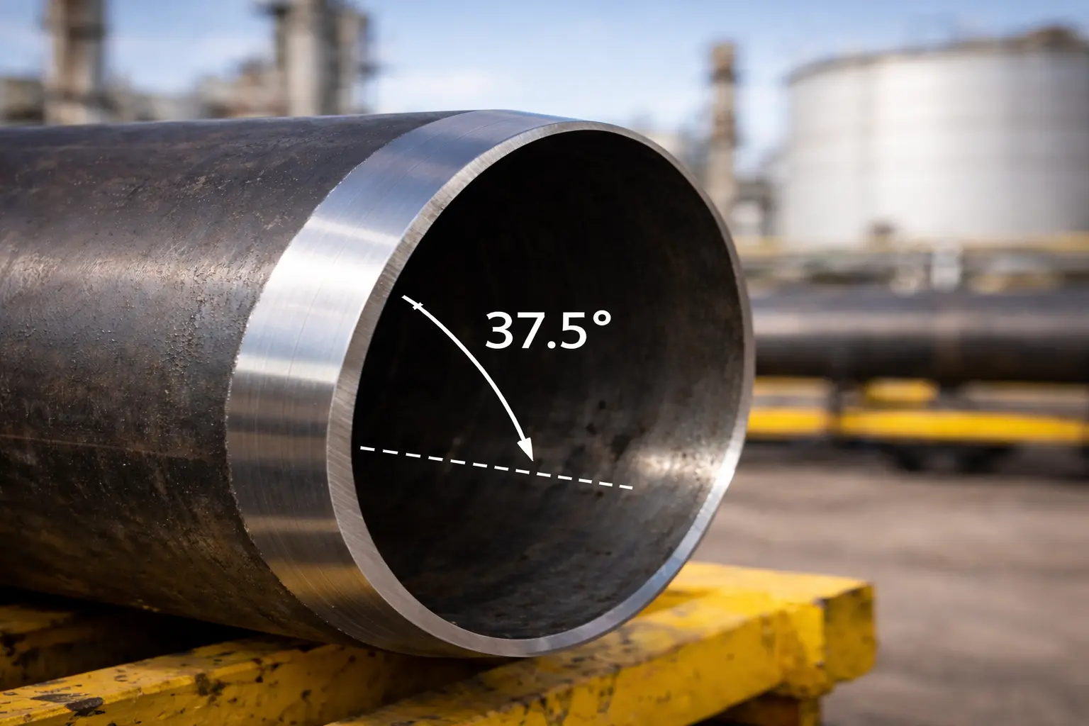
- Bevel angle (α) — between the machined face and a plane square to the pipe axis. This is what your gauge reads and what beveling machines are set to.
- Included angle — the full V the welder sees after fit-up: two bevel angles combined. 37.5° per side = 75° included.
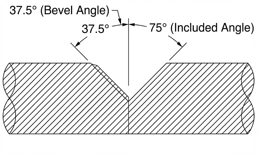 The gauge reads one side. The drawing may specify the whole V. Know which number you’re holding before you call a bevel good or bad.
Drawings and WPS documents mix the two freely. If a spec says “75°” and your gauge says “37.5°,” the bevel is correct. If you re-cut it to 75° per side, you’ve just created a weld volume problem — covered in detail in our bevel angle code requirements guide.
The Tools: Four Gauges Compared
| Tool | Reads | Accuracy | Cost | Best For |
|---|---|---|---|---|
| Protractor bevel gauge | Bevel angle | ±1° | $20–$50 | Shop and field spot checks |
| Digital angle finder | Bevel angle | ±0.2° | $30–$80 | Machine setup verification |
| Bridge cam (Cambridge) gauge | Angle, undercut, misalignment | ±0.5° | $60–$150 | Inspector-grade checks, audits |
| Calipers + formula | Width → angle (calculated) | ±1–2° | Already in your pocket | No-gauge verification anywhere |
Two buying notes from the shop floor:
- Get a gauge with a flat reference base, not just a pivot arm. The base seats on the pipe end face and gives you a repeatable reference plane. Pivot-only protractors depend on the user’s eye and wander a full degree between operators.
- A bridge cam gauge is worth it once inspectors are involved. It reads bevel angle, root face height, internal misalignment (Hi-Lo), and undercut with one tool — the same tool your inspector will use, so your numbers and their numbers agree.
How to Check a Bevel Angle Step by Step
The procedure is the same for a hand gauge or a bridge cam:
- Deburr and wipe the bevel face. Chips and burrs under the gauge blade read as degrees. Most “out of tolerance” bevels are actually dirty bevels.
- Verify the end is square first. Seat a square against the pipe OD and the end face. If the end is out of square, every angle reading taken from it is corrupted — fix squareness before arguing about angle.
- Seat the gauge base on the pipe end face, not the OD. The end face is the reference plane the bevel angle is defined from.
- Lower the blade onto the bevel face until light disappears under it, then read.
- Repeat at 12, 3, 6, and 9 o’clock. A machine with worn bearings or a loose mount cuts an angle that wanders around the circumference. Four readings within 1° of each other tells you the machine is rigid; a 3° spread tells you to stop cutting and check the clamp — our maintenance guide covers the usual suspects.
- Measure the root face separately with calipers. No angle gauge reads the land. Check it at the same four positions.
 The root face is a caliper measurement, not a gauge measurement. It’s also the dimension that actually burns you: too thin burns through, too thick won’t penetrate.
Bevel Angle Calculator
The angle, wall thickness, and root face are connected by simple trigonometry — which means you can verify a bevel with nothing but calipers, or predict what a correct bevel should measure before you cut it.
Bevel width  W = (T − RF) × tan(α)
Face length  L = (T − RF) ÷ cos(α)
Check angle  α = arctan( W ÷ (T − RF) )
Enter your numbers below. Use the first block to see what a correct bevel should measure; use the second to turn a caliper reading into the actual angle you cut.
Predict: what should this bevel measure?
Check: what angle did I actually cut?
One caveat: the formulas describe a straight V-bevel. A J-bevel has a root radius, so its geometry doesn’t reduce to a single tangent — verify J-preps against the machining drawing, not this calculator.
Acceptance Tolerances by Welding Code
“Is this bevel in tolerance?” has no universal answer — it depends on which code governs the joint and, above everything, on your qualified WPS. The common baselines:
| Code / Standard | Bevel Angle | Root Face | Notes |
|---|---|---|---|
| ASME B16.25 (via B31.3) | 37.5° ± 2.5° (wall ≤ 22 mm) | 1.6 mm ± 0.8 mm | Compound bevel above 22 mm wall |
| API 1104 (pipeline) | 30° ± 5° typical, per WPS | 1.6 mm ± 0.8 mm | 60° included is the field standard |
| AWS D1.1 (structural) | Per prequalified joint detail; fit-up typically +10°/−5° | Per joint detail | Tolerances differ per detail — read the figure |
| EN ISO 9692-1 | Ranges per joint type (e.g., 40–60° included for single-V) | Per joint type | European fabrication drawings reference these |
Full requirements, joint by joint, are in our guides on ASME B31.3, API 1104, AWS D1.1, and the standards overview if you need all of them on one page.
The pattern worth noticing: angle tolerances are generous (±2.5° to ±5°), root face tolerances are tight (±0.8 mm). Spend your measuring time accordingly — the angle rarely fails, the land frequently does.
Quick-Reference Chart: Bevel Width by Wall Thickness
What a correct bevel should measure with calipers, assuming a 1.6 mm root face. Print it, tape it to the machine:
| Wall T (mm) | W at 30° | W at 37.5° | Face length L at 37.5° |
|---|---|---|---|
| 6.0 | 2.5 mm | 3.4 mm | 5.5 mm |
| 7.1 | 3.2 mm | 4.2 mm | 6.9 mm |
| 8.6 | 4.0 mm | 5.4 mm | 8.8 mm |
| 9.5 (6” Sch 40) | 4.6 mm | 6.1 mm | 10.0 mm |
| 11.1 (8” Sch 40) | 5.5 mm | 7.3 mm | 12.0 mm |
| 12.7 | 6.4 mm | 8.5 mm | 14.0 mm |
| 15.9 | 8.3 mm | 11.0 mm | 18.0 mm |
| 20.0 | 10.6 mm | 14.1 mm | 23.2 mm |
| 25.0 | 13.5 mm | 18.0 mm | 29.5 mm |
If a measured width sits between the two columns, you’re between angles — most often a machine set to 35° by a previous shift. The multiplier table in our angles guide covers other angle values.
Five Measurement Mistakes That Fail Inspection
- Reading the angle off the OD instead of the end face. The pipe surface is curved; the end face is the defined reference plane. Seating the gauge on the OD adds error that grows with smaller pipe diameters.
- One reading instead of four. Bevels wander. An angle that’s perfect at 12 o’clock and 4° off at 6 o’clock averages “in spec” and welds like garbage. Four clock positions, every joint that matters.
- Trusting the machine dial. The angle scale on a beveling machine tells you what was set, not what was cut. Tool deflection on heavy wall and insert wear both steal angle. Verify the first part of every run — then trust the run, not the dial.
- Measuring a dirty bevel. A 0.5 mm chip under the gauge blade on a 10 mm face reads as roughly 3°. Wipe first.
- Checking angle but not root face. The angle has a ±2.5° window; the root face has ±0.8 mm. Nearly every burn-through and lack-of-penetration reject is a land problem that an angle gauge was never going to catch.
There’s a reason machine-cut bevels sail through these checks and grinder bevels don’t: a rigid machine produces the same angle at all four clock positions by construction. If your crew is spending real time measuring, re-grinding, and re-measuring, the fix isn’t a better gauge — it’s a pipe beveling machine that makes the measurement boring. Our angle grinder vs machine comparison puts numbers on that trade.
Questions about holding tolerance on a specific material or wall thickness? Talk to our engineers — machining bevels that pass inspection is the entire business.