Why Pipeline Beveling Is Deceptively Simple
API 1104 is the shortest welding code most pipeline welders will ever work under. Compared to ASME Section IX, B31.3, or AWS D1.1, the bevel requirements fit on a single page. One standard bevel angle. One root face dimension. One root gap specification. Done.
That simplicity is a trap.
I’ve supplied pipe beveling equipment to pipeline contractors on six continents, and the pattern is always the same: the contractor assumes pipeline bevel prep is trivial because the code is simple, under-invests in prep quality, and then bleeds money on repair welds when 10–15% of their joints fail radiography.
Here’s the reality: on a 100-kilometer cross-country pipeline with 4,000+ field welds, a 5% repair rate versus a 2% repair rate is the difference between finishing on schedule and blowing your budget by hundreds of thousands of dollars. And the root cause of that 3% gap is almost never the welder. It’s the bevel.
This guide covers what API 1104 actually requires for bevel geometry, where the code gives you latitude and where it doesn’t, and what I see pipeline crews getting wrong—especially in the field where conditions aren’t as forgiving as the fabrication shop.
What API 1104 Actually Specifies
API 1104 (Welding of Pipelines and Related Facilities) is published by the American Petroleum Institute and governs welding on cross-country pipelines, station piping, and offshore pipeline systems. It’s the default code for virtually all oil and gas transmission pipeline construction worldwide.
For bevel prep, the relevant sections are:
- Section 5 — Specification for Welding Procedures: Defines the essential variables including joint design
- Section 7 — Design and Preparation of a Joint for Production Welding: The actual bevel geometry and fit-up requirements
- Appendix B — In-Service Welding: Special considerations for hot tapping and in-service repair (different fit-up rules)
Unlike ASME codes that reference ASME B16.25 for weld end prep details, API 1104 keeps it self-contained. The bevel geometry is specified directly in the code—which makes it simpler to reference but also means there’s less room for interpretation.
The parameters API 1104 controls
| Parameter | What the code specifies | Why it matters for your welder |
|---|---|---|
| Bevel angle | Per qualified WPS (typically 30° ± 5° bevel = 60° ± 10° included) | Controls root pass access and weld volume |
| Root face (land) | Per qualified WPS (typically 1.6mm / 1/16”) | Controls root pass penetration depth |
| Root gap (opening) | Per qualified WPS (typically 1.6mm / 1/16”) | Controls root pass fusion and bead profile |
| Hi-Lo (misalignment) | Maximum per Section 7.2 (typically 1.6mm / 1/16”) | Controls root pass uniformity and UT/RT acceptability |
| Surface condition | Clean, free of scale, rust, and contaminants | Prevents porosity and inclusions |
Notice the pattern: almost every dimension is 1/16” (1.6mm). Pipeline welders joke that 1104 is the “sixteenth-inch code.” That simplicity is intentional—pipeline welding happens in ditches, on mountainsides, in −40° weather. The code is designed to be executable in field conditions by qualified welders who don’t have shop-floor luxuries.
But “simple” doesn’t mean “forgiving.” When every critical dimension is 1.6mm, there’s very little margin for error.
The Standard Bevel Everyone Thinks They Know
The workhorse API 1104 joint is the standard V-groove bevel with a 60° included angle (30° per side). If you’ve been anywhere near a pipeline right-of-way, you’ve seen it a thousand times:
- Bevel angle: 30° ± 5° (per side)
- Included angle: 60° ± 10°
- Root face: 1.6mm ± 0.8mm (1/16” ± 1/32”)
- Root gap: 1.6mm ± 0.8mm (1/16” ± 1/32”)
These are the “typical” dimensions. API 1104 actually defers to the qualified welding procedure specification (WPS) for exact values—if your WPS qualifies a different bevel angle, the code permits it. But 30°/60° is so dominant in pipeline work that it’s essentially the industry standard.
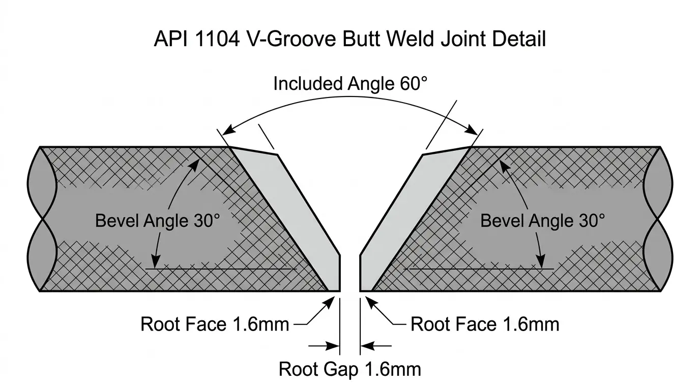 API 1104 standard V-groove joint geometry. Three dimensions—bevel angle, root face, root gap—all centered on 1.6mm. Simple on paper, unforgiving in execution.
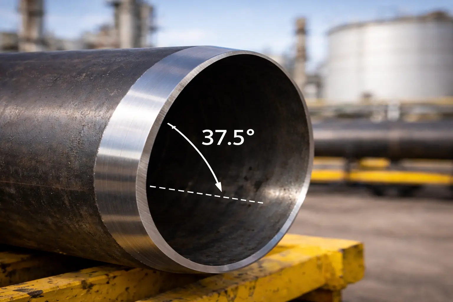
Why 30° and not 37.5°?
If you’ve read the ASME B31.3 beveling guide or the pipe bevel angles article, you know that process piping typically uses a 37.5° bevel (75° included). Pipeline work uses 30° (60° included). The reason is practical:
Pipeline welding is predominantly downhill with cellulosic electrodes (E6010/E8010) or low-hydrogen vertical-down (E9010). The 60° included angle is wide enough for root pass access with a stringer bead but narrow enough to minimize fill passes. On a 12.7mm (0.500”) wall X65 pipeline, a 60° V-groove takes roughly 3 fill passes after the root and hot pass. A 75° groove would take 4–5. Across 4,000 joints, that extra pass adds up to weeks of welding time.
Process piping uses 37.5° because it’s welded in all positions with different techniques. The wider groove gives more access for weaving beads in the overhead position. Pipeline welders don’t weave—they run stringers downhill. Different technique, different optimal geometry.
This is why you can’t just grab “standard pipe bevel” numbers and apply them to pipeline work. The codes look similar but serve fundamentally different welding approaches.
Root Gap: The Variable That Kills Pipelines
If I could fix one thing about pipeline bevel prep worldwide, it would be root gap consistency.
Root gap is the single most influential variable in pipeline root pass quality. More than bevel angle. More than root face. More than electrode selection. Here’s why:
A pipeline root pass (the first pass that bridges the gap between the two pipe ends) is a precision operation. The welder is running E6010 or equivalent at controlled amperage, maintaining a specific arc length, and manipulating the electrode to create a root bead that penetrates both pipe walls and forms a smooth internal profile. The root gap determines:
- Whether the arc can reach both bevel faces: Too tight, and the arc can’t get into the root. The welder gets lack-of-fusion on one or both sides.
- How much metal the arc has to bridge: Too wide, and the welder gets burn-through, suck-back, or excessive internal reinforcement.
- Bead profile uniformity: Inconsistent gap = inconsistent bead. The internal profile goes from concave to convex along the joint.
What “1.6mm ± 0.8mm” actually means in the ditch
The nominal 1.6mm (1/16”) root gap with a ±0.8mm tolerance means you’re working in a window of 0.8mm to 2.4mm. That’s a total range of 1.6mm—roughly the thickness of a nickel.
On paper, that tolerance seems generous. In a ditch with 48” pipe sitting on skids, it’s brutal.
Here’s what happens in practice: the pipe gang cuts and bevels joints at the stringing site or the pipe yard. The bevels look fine. The pipe is strung along the right-of-way, lifted into the ditch, and aligned by the lineup crew. But pipe is never perfectly round—especially after transport and handling. Large-diameter pipe (24”+) can be slightly oval. When you clamp two slightly oval pipes together, the root gap varies around the circumference.
At the 12 o’clock position, the gap might be 1.5mm. At 3 o’clock, 2.2mm. At 6 o’clock, 0.9mm. All within tolerance—but the welder is chasing a moving target around the clock. Every 15° of rotation, the gap changes, and the welder has to adjust amperage, travel speed, and manipulation.
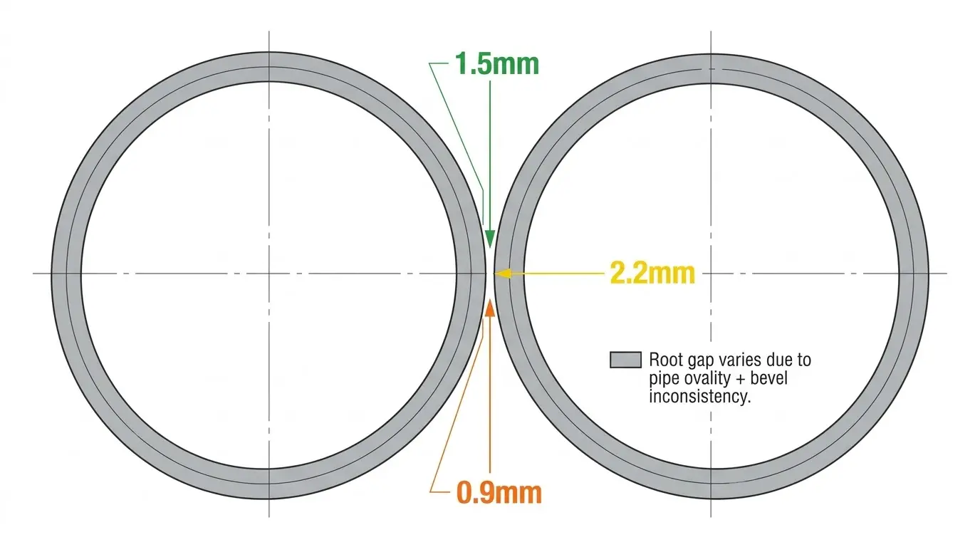 Root gap variation on a 36” pipeline field joint. Pipe ovality and bevel inconsistency combine to create a gap that changes every few degrees around the clock—the welder compensates, but the RT film doesn’t lie.
This is why the best pipeline welders in the world still get occasional root defects. They’re not making mistakes—they’re compensating for inconsistent fit-up that starts with inconsistent bevel geometry.
Root Face (Land) Thickness and the Burn-Through Line
The root face—the flat portion at the nose of the bevel—is API 1104’s simplest dimension and its most unforgiving.
Standard spec: 1.6mm (1/16”) ± 0.8mm.
That means 0.8mm to 2.4mm. The difference between the bottom and top of that range changes the welding physics completely:
- 0.8mm root face: The welder has very little metal to burn through. Easy root penetration, but high burn-through risk. One moment of hesitation or slightly high amperage, and you’ve got a hole that has to be repaired.
- 2.4mm root face: The welder has to push through significantly more metal. Root penetration becomes difficult, especially in the overhead (6 o’clock) position where gravity works against the puddle. Lack-of-penetration defects become likely.
The sweet spot is 1.2–1.8mm. Most experienced pipeline welders will tell you this without referencing the code—they’ve learned it by burning through a thousand root passes.
Where root face consistency breaks down
The root face is the part of the bevel that’s hardest to control with field beveling methods. Here’s why:
Flame-cut bevels (oxy-fuel with Bug-O or similar track): The flame cuts the bevel angle reasonably well, but the landing (root face) is formed by stopping the cut at a precise depth. In practice, the depth varies by 0.5–1.5mm along the circumference because the torch tip-to-work distance isn’t perfectly constant on a round pipe. You end up with a root face that varies from 1mm to 3mm around the clock.
Grinding: Some crews grind the root face after flame cutting to “clean it up.” This makes it worse, not better. A grinding disc removes material unevenly—you get thin spots and thick spots that look uniform to the eye but measure differently with a gauge.
Machine beveling: A split frame clamshell beveling machine holds the cutting tool at a fixed radial depth as it travels around the pipe. The root face is determined by the tool geometry and the depth setting—both of which are constant. The root face variation is typically less than 0.3mm around the full circumference. That’s the difference between “within tolerance” and “within the sweet spot.”
Hi-Lo Misalignment: Where Beveling Meets Fit-Up
Hi-Lo (internal misalignment between two pipe ends) isn’t strictly a beveling parameter—it’s a fit-up parameter. But poor beveling directly causes hi-lo problems, so it belongs in this discussion.
API 1104 Section 7.2 limits hi-lo to 1.6mm (1/16”) for butt welds. Some client specifications (especially for sour service or pipelines requiring 100% automatic UT) tighten this to 1.0mm or even 0.5mm.
How bevel quality affects hi-lo
If the pipe end isn’t cut square before beveling, the wall thickness at the bevel varies around the circumference. When you align two pipes with uneven wall thickness at the joint, you get hi-lo—even if both pipes are perfectly round.
Example: A 24” × 12.7mm wall pipe has a bevel cut slightly off-square—the wall at 12 o’clock is 12.5mm, and at 6 o’clock is 13.0mm. The mating pipe has the same issue in the opposite direction. At the worst point, you’ve got 1.0mm of hi-lo from bevel geometry alone—before any pipe ovality or clamp misalignment contributes.
On projects with tight hi-lo specs, I consistently see that crews using machine-cut bevels spend less time on alignment because the pipe ends are square and consistent. The lineup clamp does its job more efficiently when the starting geometry is predictable.
Field Beveling vs. Shop Beveling: Different Worlds
This is the part that shop fabricators underestimate and pipeline contractors live with every day.
Shop beveling advantages
In a pipe fabrication shop (spool shop), you have:
- Level work surfaces
- Overhead cranes for pipe handling
- Climate control (or at least a roof)
- Stationary beveling machines bolted to the floor
- Time to measure and adjust before committing to a cut
Shop beveling for pipeline pre-fabrication (station piping, meter runs, launcher/receiver assemblies) is essentially the same as process piping fabrication. Standard internal-mount pipe bevelers handle it efficiently.
Field beveling reality
On a pipeline right-of-way, you have:
- Pipe sitting on timber skids in a ditch or on the ground surface
- Wind, rain, snow, dust, and temperature extremes
- Limited power (typically hydraulic from a welding rig or a standalone power unit)
- Time pressure (the pipe gang, lineup crew, and welding crew are sequential—delays cascade)
- No second chances (once the pipe is in the ditch, re-beveling means lifting it back out)
This is why field beveling equipment has to be fundamentally different from shop equipment. You can’t roll a lathe-type beveler down a pipeline right-of-way. You need equipment that:
- Clamps to the outside of the pipe (no ID access in a ditch)
- Runs on hydraulic power (available from welding rigs)
- Sets up in minutes, not hours
- Produces consistent results regardless of operator fatigue or weather
- Handles the full range of pipe diameters on the project
What I See Fail RT on Pipeline Projects
After years of working with pipeline contractors, here are the bevel-related root causes of radiography rejects that come up again and again:
1. Incomplete penetration from thick root face
The most common API 1104 bevel defect. The root face is 2.5–3mm instead of the specified 1.6mm. The welder can’t burn through consistently, especially in the overhead segment. RT shows a dark line at the root—incomplete penetration.
Why it happens: Flame-cut bevels with inconsistent depth control. The operator set the cut depth for 1.6mm root face, but the torch-to-pipe distance varied and left thick spots.
The cost: Each repair requires cutting out the defect, re-prepping the cavity, and re-welding—typically 2–4 hours of welder time plus re-inspection. On a project with 4,000 welds and a 5% reject rate, that’s 200 repairs × 3 hours average = 600 hours of welder time that produces zero progress.
2. Burn-through from thin root face
The inverse problem. Root face too thin (under 0.8mm) in sections, leading to burn-through. The welder blows through the root face, creating holes or excessive internal reinforcement (icicles) that fail RT.
Why it happens: Over-grinding the root face to “clean up” a flame cut, or machine bevel set too deep.
3. Lack of fusion from tight root gap
Root gap under 0.8mm in sections. The electrode can’t reach both bevel faces simultaneously. One side fuses, the other doesn’t. RT shows a linear indication along the root on one side of the joint.
Why it happens: Pipe ovality combined with inconsistent bevel geometry. The lineup clamp pulls the pipe round, but the root gap closes unevenly.
4. Porosity at the root from surface contamination
Not strictly a geometry issue, but a bevel quality issue. Oxy-fuel cutting leaves an oxide layer on the bevel face. If not removed before welding, the oxide decomposes and produces porosity in the root pass.
Why it happens: The crew assumes the bevel is “clean enough” after flame cutting. On carbon steel pipe, the oxide layer isn’t always visible—it looks like bare metal. But the oxygen-enriched surface produces gas when the arc hits it.
The fix: Either grind the bevel face (adds time) or use a cold cutting method that doesn’t produce an oxide layer. Mechanical cutting with carbide tooling—the kind used in split frame pipe cutting and beveling machines—produces a clean metallic surface ready for welding.
5. Root face variation causing inconsistent root bead profile
The subtle one. Root face varies from 1.0mm to 2.5mm around the circumference. Each dimension individually is within tolerance. But the welder adjusts technique for the thick spots and then gets burn-through at the thin spots—or vice versa.
Why it happens: This is the inherent limitation of flame cutting on pipe. The torch follows a track, but the standoff distance to a round pipe changes constantly. The cut depth varies, and so does the root face.
Equipment That Holds API 1104 Tolerances in the Field
For pipeline work under API 1104, the equipment choice depends on where the beveling happens and the pipe diameter range.
Pipeline mainline: Split Frame Clamshell Machines
The Split Frame Series is purpose-built for pipeline field beveling. It’s a clamshell-type machine that clamps around the pipe OD, requiring no internal access—critical for in-ditch operations.
- Pipe range: 89mm to 1830mm OD (3.5” to 72”)
- Drive: Pneumatic or hydraulic (compatible with pipeline welding rig power units)
- Bevel angle: Adjustable, preset to match your WPS (30° ± 0.5° achievable)
- Root face: Controlled by tool geometry and depth setting—consistent within 0.3mm around the circumference
- Setup time: Under 15 minutes for experienced crew
- Cutting method: Cold mechanical cutting with carbide inserts—no HAZ, no oxide layer, no post-cut grinding
For a pipeline spread running 24” or 36” mainline, the Split Frame replaces the oxy-fuel bevel crew entirely. The bevel quality is categorically different—not incrementally better, but fundamentally consistent in a way that flame cutting cannot match.
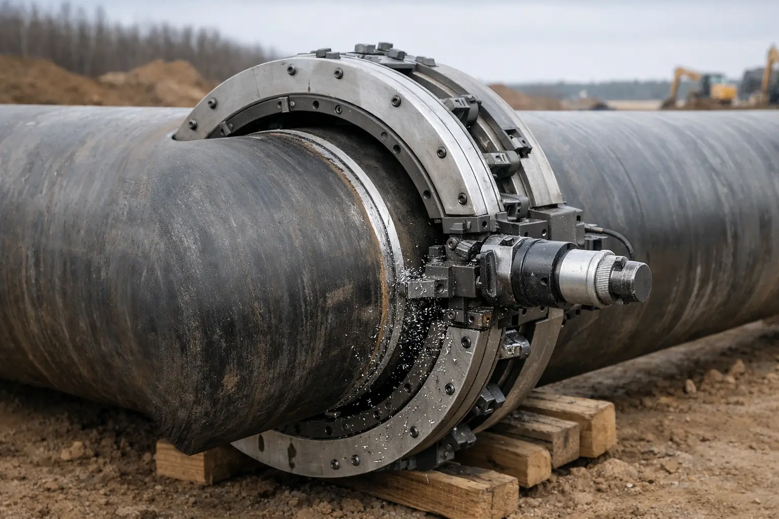 Split Frame clamshell machine on a 36” pipeline right-of-way. OD-clamp design means no internal access required—critical when the pipe is already in the ditch.
What this means for your RT reject rate: contractors who switch from flame cutting to machine beveling on pipeline mainline work consistently report reject rates dropping from 5–8% to 1–3%. The welders are the same. The WPS is the same. The electrodes are the same. Only the bevel changed.
Station piping and pre-fabrication: ID-Mount Beveling Machines
For station piping, meter runs, launcher/receiver assemblies, and tie-in spools fabricated in a shop or laydown area, the pipe ends are accessible and the work is stationary—which means you can use lathe-type beveling machines that deliver higher precision than any field method.
The ISE-T internal-mount beveler handles the typical station piping range (2”–10” NPS) and consistently produces bevels tight enough for downstream automatic orbital welding—a precision level that matters when your client spec calls for 100% RT on all station piping joints.
Large-diameter and offshore: Planetary Cutting Machines
For large-diameter pipeline (30”+) where the split frame approach needs supplementing, or for offshore pipeline construction where setup time is critical, the Planetary pipe cutting machine offers OD-mount cutting and beveling with the rigidity needed for thick-wall pipe.
The Bottom Line
API 1104 beveling requirements are the simplest in the welding code world—but simplicity doesn’t equal forgiveness. When every critical dimension is 1.6mm with a ±0.8mm tolerance, you’re working in a window where small inconsistencies in bevel prep cascade into root pass defects that show up on every radiograph.
Here’s my assessment after years of equipping pipeline contractors:
- The bevel angle is rarely the problem. Most cutting methods get within ±5° consistently. It’s the root face and root gap that kill you.
- Root face consistency is the highest-value improvement you can make to your pipeline bevel prep process. A 0.3mm variation versus a 1.5mm variation is the difference between “the welder adjusts” and “the welder can’t compensate.”
- Field conditions amplify every bevel imperfection. What’s marginal in a shop becomes rejectable in a ditch at 6 o’clock position in January.
- Machine beveling isn’t a luxury on pipeline work—it’s the minimum standard for contractors who are serious about schedule and repair rates.
If you’re running a pipeline spread and want to evaluate whether upgrading your bevel prep process makes sense, send me:
- Pipe diameter and wall thickness range for your current project
- Current beveling method (oxy-fuel, grinder, existing machine)
- Current RT/UT reject rate (even a rough estimate helps)
- Number of field welds on the project
- WPS bevel specifications (angle, root face, root gap)
I’ll calculate the potential repair cost savings and tell you whether the equipment investment pencils out—or if your current process is genuinely adequate for your quality targets.
Related reading:
- Pipe Bevel Angles & Code Requirements — How API 1104 angles compare to ASME and AWS specifications
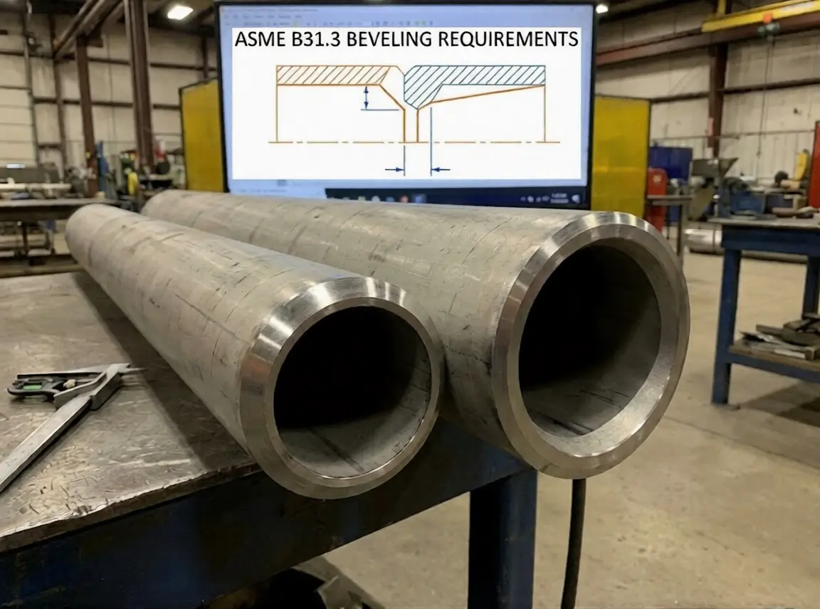
- ASME B31.3 Beveling Requirements — Process piping code comparison for pipeline station piping
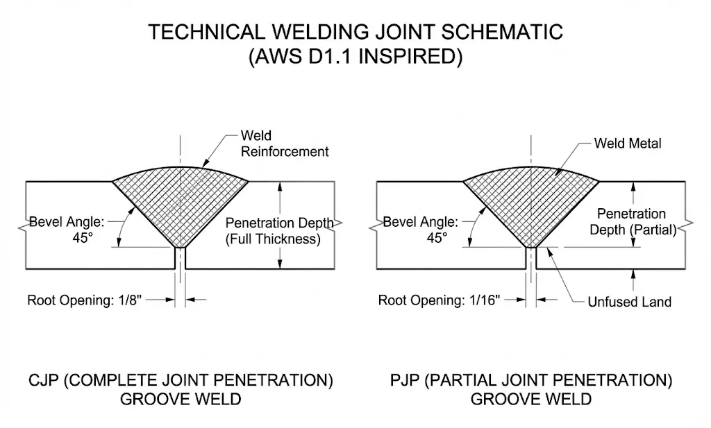
- AWS D1.1 Structural Steel Beveling — How structural steel code tolerances differ from pipeline
- Cold Cutting vs Thermal Cutting — The metallurgical case for mechanical beveling on pipelines
- Oil & Gas Pipe Beveling Solutions — Our approach to pipeline and refinery pipe preparation
Based on API 1104, 22nd Edition (Welding of Pipelines and Related Facilities) and field experience with pipeline contractors across North America, the Middle East, Southeast Asia, and Central Asia. Bevel tolerances referenced from typical qualified WPSs; specific project requirements may differ. Always verify requirements against your project-specific WPS and client specifications.