The 2 AM Phone Call
A power plant in Indonesia commissioned a new boiler in late 2023. The main steam line was P91 — 14-inch Schedule 160, exactly the material the design called for. The fabricator plasma-cut the field joints, ground the bevels by hand, ran PWHT on every weld, and passed every radiograph. Hydro test passed. First fire passed. Three days into commissioning, one of the welds let go during a steam ramp. No one was hurt. The plant lost six weeks of schedule and roughly $4 million in delayed power purchase agreements.
I got the phone call at 2 AM Beijing time. The metallurgical report came back two weeks later: Type IV cracking initiated at a region of untempered martensite at the weld toe — exactly where the plasma cut had left a hardened layer that the PWHT cycle couldn’t fully temper. The weld procedure was correct. The PWHT was correct. The radiograph showed nothing because the crack initiated after the X-ray and grew under stress.
The cause was a cutting decision made three weeks before the weld was struck.
I have watched this exact failure mode three times in different countries. Every single time, the root cause traces back to the same thing: thermal cutting on P91 leaves a band of metal that no normal welding or PWHT procedure can fix. If you don’t remove it before welding, it becomes a crack initiation site that may not show itself until the plant is running.
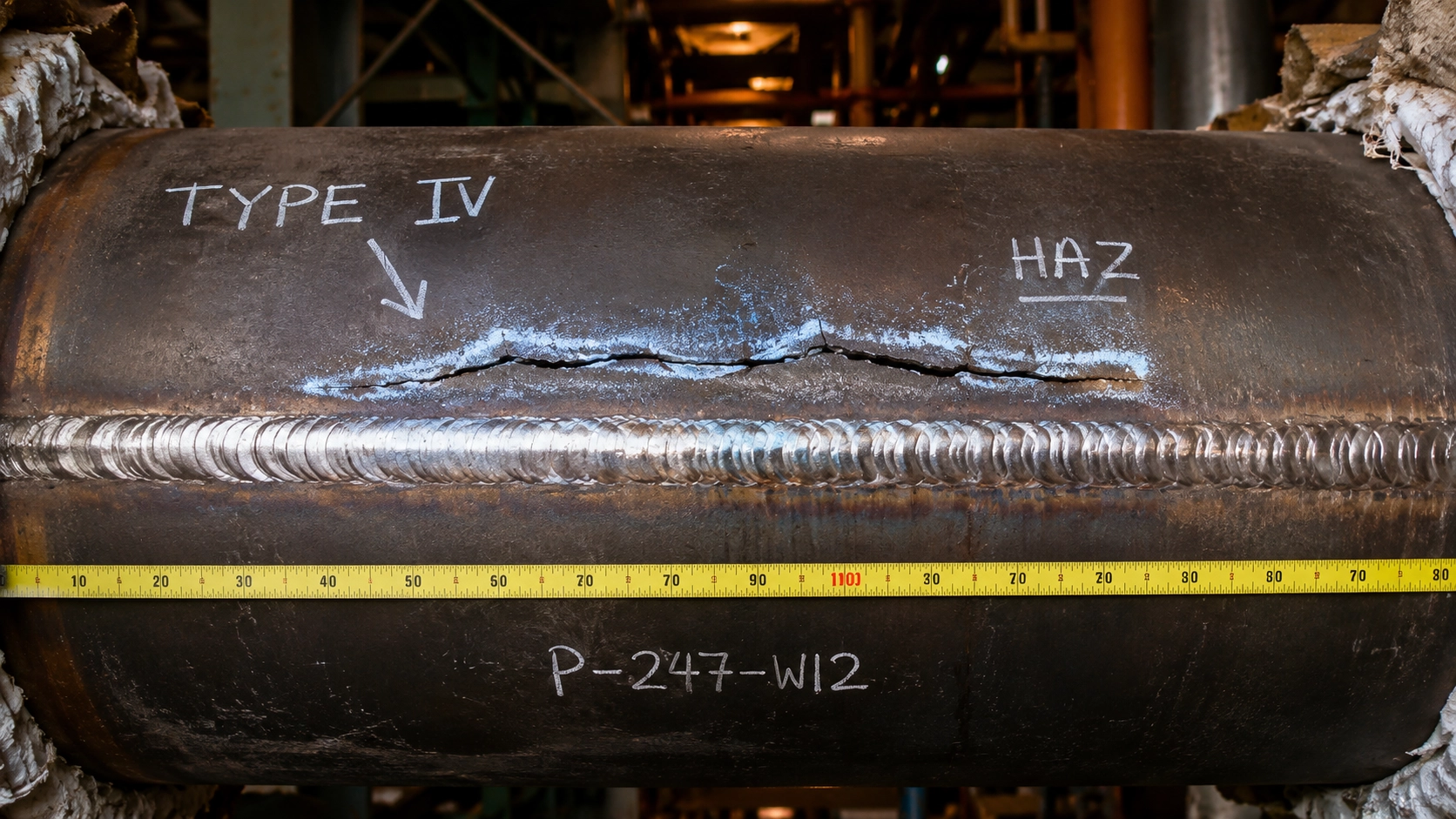 Type IV crack in a P91 main steam weld discovered during commissioning. The crack initiated at a band of untempered martensite left by the plasma cut three weeks earlier and propagated under thermal stress. The weld itself was code-compliant; the bevel preparation was not.
What P91 Actually Is
P91 (ASTM A335 Grade P91, also called Grade 91 or T91 in tube form) is a 9Cr-1Mo-V-Nb-N martensitic alloy steel developed in the 1980s for high-temperature, high-pressure power and petrochemical service. Its design service envelope is roughly 540–625°C and pressures up to 30 MPa — the conditions in modern supercritical and ultra-supercritical boilers, main steam lines, hot reheat headers, and refinery hydrocracker feed piping.
The reason P91 works in that envelope is not the chemistry alone — it’s the microstructure. P91 is designed to operate as tempered martensite: a fine-grained structure of carbide-stabilized martensite where the carbides (M₂₃C₆ and MX-type vanadium-niobium precipitates) pin the dislocations and resist creep deformation at 600°C for decades.
Three things destroy this microstructure:
- Heat above ~830°C followed by uncontrolled cooling — this re-forms fresh untempered martensite, which is hard and brittle
- Heat in the 600–830°C range without proper hold time — this dissolves the precipitates without re-forming the stable structure
- Hydrogen exposure on untempered martensite — causes delayed cracking, sometimes weeks after the event
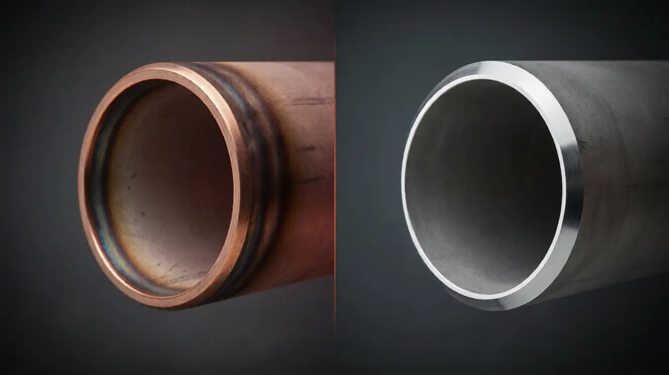
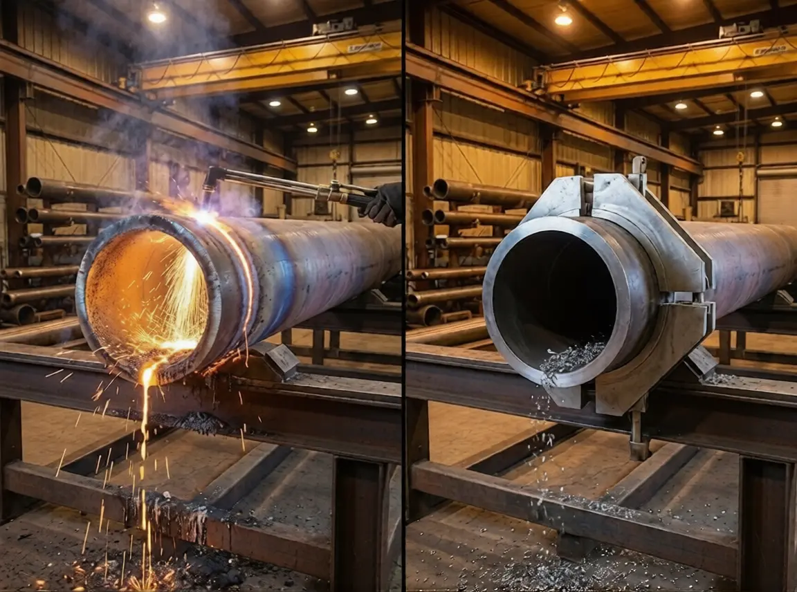
Every thermal cutting method does exactly the first thing. The peak temperature at the cut face on oxy-fuel cutting is 2,800–3,200°C; on plasma it’s 20,000–30,000°C. The assist gas then quench-cools the metal from above its austenitizing temperature in seconds. You have just made a thin layer of as-quenched martensite at the bevel face — the worst possible microstructure for P91, on the exact surface that will become the weld root.
Cold cutting generates a maximum temperature of under 50°C at the tool-workpiece interface. There is no austenitizing, no quenching, and no microstructure change. The metal at the bevel face after cold cutting is metallurgically identical to the metal 100mm away from the bevel.
Why Heat Cutting Creates Crack Sites
The thermal damage from cutting interacts with welding and PWHT in a way that fools a lot of fabricators. Here’s the sequence that produces the failures I’ve seen:
Step 1 — The cut creates as-quenched martensite
Plasma or oxy-fuel cuts the pipe. A 1–3mm deep zone at the bevel face is now untempered martensite, with hardness of 380–450 HV depending on cooling rate. The metal looks fine to the eye. It welds fine. It X-rays fine.
Step 2 — Welding adds heat from the other direction
The root pass goes in. It heats the bevel face from the weld side, but only briefly — not long enough to fully temper a 2–3mm thick martensite layer. Subsequent passes drift further from the bevel face. The original cut-face martensite stays largely untempered.
Step 3 — PWHT partially tempers but doesn’t fix it
The standard PWHT for P91 is 760°C ± 14°C for 2–4 hours (per ASME B31.1 Table 132). At that temperature, fresh untempered martensite will partially temper — but the carbide precipitation that gives P91 its creep strength requires the original solution-and-temper heat treatment from the mill, not a field PWHT. What you get is “lightly tempered” martensite at the cut face, still significantly harder and more brittle than the surrounding base metal.
Step 4 — Hydrogen migrates and cracks form
Welding always introduces some diffusible hydrogen — from moisture in flux, atmospheric humidity, contamination on the bevel face. Hydrogen migrates preferentially into hard, high-stress regions. The lightly-tempered martensite band at the former cut face is exactly that region. Cracks form along the boundary between the heat-affected band and the surrounding metal.
Step 5 — The crack waits
This is the brutal part. Hydrogen-induced cracking in chrome-moly is often delayed by 8 hours to 3 weeks after welding. The plant passes inspection. The plant goes into commissioning. The crack reaches critical size under thermal stress, and the plant trips — or worse.
This sequence is well-documented in EPRI reports, AWS literature, and the metallurgical post-mortems on every major P91 boiler failure of the last 20 years. The cleanest defense is not removing it post-weld — it’s not creating it in the first place.
The Hardness Trap: 265 HV vs Reality
Every credible code or operator specification for P91 weld prep has a hardness ceiling. Hit the ceiling and the joint passes. Exceed it and the joint fails — sometimes by code rejection, sometimes by service failure later.
| Spec / Code | Max Hardness on P91 HAZ | Notes |
|---|---|---|
| ASME B31.1 (Power Piping) | 265 HV | Most common power plant reference |
| ASME B31.3 (Process Piping) | 248 HV (some classes), 265 HV (others) | Service-class dependent |
| EN 13480 | 265 HV (≈ 25 HRC) | European power piping |
| Shell DEP / Exxon GP | 250 HV | Tighter than code |
| Major EPC project specs (typical) | 248–265 HV | Project-specific |
Now compare to actual measured hardness at the cut face by method, on 30mm wall P91 samples I’ve tested from customer post-mortems:
| Cutting Method | Peak Hardness at Cut Face | Hardness 5mm In | Status vs 265 HV limit |
|---|---|---|---|
| Oxy-fuel (with iron powder additive) | 410–460 HV | 280–310 HV | Fails by 145–195 HV |
| Plasma (compressed air) | 380–420 HV | 270–290 HV | Fails by 115–155 HV |
| Plasma (nitrogen shield) | 350–390 HV | 260–280 HV | Fails by 85–125 HV |
| Laser (fiber, N₂ assist) | 320–360 HV | 240–260 HV | Fails by 55–95 HV |
| Cold cutting (carbide tooling) | 200–220 HV | 200–220 HV | Passes — base metal value |
The base metal hardness of properly heat-treated P91 is 200–220 HV. Cold cutting preserves it exactly. Every thermal method exceeds 265 HV at the cut face, and the only fix is mechanical removal of the affected layer.
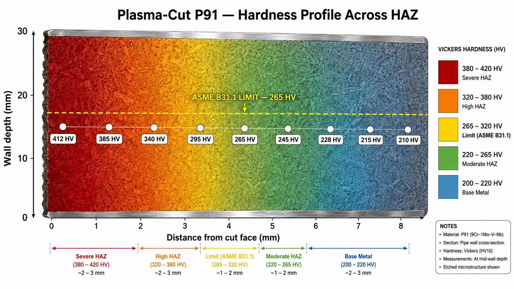 Vickers hardness measurements across a plasma-cut P91 sample, plotted on the cross-section. The red zone exceeding 380 HV is 2.5mm deep at the cut face. ASME B31.1 limit (265 HV, yellow line) is exceeded for 3.8mm. The full hardened band must be removed before welding to bring the joint into code.
The hardness data is unambiguous. The argument for cold cutting on P91 isn’t aesthetic preference — it’s the only method that produces a bevel face within the code-allowed hardness range without secondary machining.
The PWHT You Didn’t Plan For
Here’s where the project schedule gets hurt: when thermal cutting creates a hardened bevel, two things can fix it before welding. Both cost real money.
Option A — Mechanical removal
Grind or machine back the entire bevel face to at least 4mm depth past the hardness peak, then re-test by portable hardness tester to verify acceptance. On a typical 14-inch P91 main steam pipe, this takes 25–40 minutes per joint with a die grinder, plus 10 minutes for hardness verification, plus 15% rework rate where the first grind doesn’t fully remove the affected zone.
Total real time per joint: 45–60 minutes of skilled labor to undo what the plasma cutter did in 90 seconds.
Option B — Pre-weld localized PWHT
Wrap the bevel area with induction or resistance heating coils, ramp to 760°C, hold for 2 hours, ramp down with controlled cooling. This effectively re-tempers the martensite back below the hardness limit. Then weld normally and run a second PWHT after welding.
The pre-weld PWHT alone takes 6–8 hours per joint including ramp/hold/cool and setup. Equipment occupancy is significant. On a project with 80 P91 welds, that’s 480–640 hours of additional schedule that wasn’t in the original plan.
Option C — Cold cut the bevel and skip both
The Split Frame or ISE II-Model cold-machines the bevel in 15–25 minutes per joint with no hardness change, no pre-weld treatment, and no rework. The standard post-weld PWHT still applies — that’s a metallurgical requirement of the weld itself, not the cut. But the additional cost of fixing the cut goes to zero.
Total cost per P91 joint — plasma vs cold cut
| Step | Plasma + Mechanical Removal | Cold Cut (Split Frame) |
|---|---|---|
| Setup | 8 min | 10 min |
| Cut | 3 min | 18 min |
| Grind sensitized/hardened layer | 35 min (incl. 15% rework) | — |
| Hardness verification | 10 min | Not required |
| Machine final bevel geometry | 12 min | Included in cut |
| Bevel cleanup before welding | 5 min | 3 min |
| Total time per joint | ~73 min | ~31 min |
| Consumables per joint | $12–$20 (grinding + plasma) | $2–$4 (carbide insert wear) |
| Rejection risk on inspection | 8–15% | < 1% |
On a typical EPC project with 80 P91 main steam joints, switching to cold cutting saves roughly 55 labor-hours and $1,000 in consumables — and removes the multi-million-dollar schedule risk of a delayed-crack failure during commissioning.
P22, P5, P9: The Cousins
P91 gets most of the attention because it’s the dominant material in modern supercritical power plants. But the entire chrome-moly family behaves similarly — heat-cut and you create untempered martensite at the cut face. Some are more forgiving than others.
| Alloy | Cr / Mo Content | Typical Service | Cut-Face Hardness Risk | Hardness Limit (ASME) |
|---|---|---|---|---|
| P11 (1¼Cr-½Mo) | 1.25% Cr, 0.5% Mo | Conventional power, mild creep service | Moderate | 225 HV |
| P22 (2¼Cr-1Mo) | 2.25% Cr, 1% Mo | Hot reheat, subcritical boilers | High | 241 HV (some specs) |
| P5 (5Cr-½Mo) | 5% Cr, 0.5% Mo | Refinery hydrocrackers | High | 241 HV |
| P9 (9Cr-1Mo) | 9% Cr, 1% Mo | Older high-temp service | Very high | 248 HV |
| P91 (9Cr-1Mo-V-Nb) | 9% Cr, 1% Mo, +V/Nb | Supercritical power, modern HRSG | Critical | 265 HV |
| P92 (9Cr-½Mo-W-V-Nb) | 9% Cr, 0.5% Mo, +W/V/Nb | Ultra-supercritical, USC boilers | Critical | 265 HV |
P91 and P92 are the most demanding because their high creep strength depends on a precise carbide precipitate distribution that takes hours of controlled heat treatment at the mill to develop. Disrupt it with thermal cutting and you cannot fully restore it in the field.
P22 and P11 are more forgiving — they have lower hardenability and the as-quenched martensite at the cut face responds well to a single PWHT cycle. But “more forgiving” is not “no problem.” On a recent hydrocracker feed line project (P22, Schedule 80, 16-inch), the contractor plasma-cut and ground all bevels per their carbon steel procedure. Eight welds out of 47 failed post-PWHT hardness testing, each requiring grind-and-reweld. The total rework cost on a single piping spool exceeded $40,000.
For any chrome-moly application — P11 through P92 — the safest path is cold cutting. The marginal cost of cold cutting versus plasma is small. The cost of rework, schedule delay, and service failure is not.
Cold Cutting P91 the Right Way
Cold cutting P91 is not the same as cold cutting carbon steel. The tooling, feed rates, and machine rigidity all need to step up. Here’s what works in practice.
Machine selection by wall thickness
| Wall Thickness | Pipe Size Range | Recommended Machine | Cycle Time per Joint |
|---|---|---|---|
| ≤ 25mm | Up to 12” (DN300) | ISE T-Model | 6–10 min |
| 25–50mm | 6”–24” (DN150–DN600) | ISE II-Model | 12–20 min |
| 50–75mm | 12”–36” (DN300–DN900) | ISE II-Model heavy | 18–30 min |
| 75–120mm | Main steam lines, headers | Split Frame (hydraulic) | 25–45 min |
| > 120mm | Boiler drums, large headers | Split Frame with reinforced frame | 40–70 min |
Tooling and parameters
P91 is harder to machine than carbon steel — comparable to mild stainless. The standard tooling that ships with most beveling machines is optimized for carbon and low-alloy steel and wears out fast on 9Cr material. Specify when ordering:
- Inserts: TiAlN-coated tungsten carbide, grade rated for 200–400 HB alloy steels. Standard P-grade inserts wear 3–4x faster than carbon steel and produce poor surface finish. Coated grades roughly triple insert life on P91.
- Feed rate: 0.05–0.08mm/revolution, roughly 30% lower than carbon steel
- Depth of cut per pass: 0.5–1.5mm depending on machine rigidity (lower on portable, higher on stationary)
- Coolant: Flood coolant is ideal but rarely available on field machines; mist coolant or cutting fluid stick is acceptable. Avoid chlorinated coolants — they can leave deposits that interfere with subsequent welding and PWHT.
Clamping and rigidity
P91 tends to chatter if the machine isn’t rigidly clamped. Symptoms are wavy bevel surface and rapid insert wear. On portable ID-mount machines, ensure clamping jaws make full contact and torque to specification; on split-frame machines, verify the frame closure bolts are fully torqued before starting the cut. A 5% increase in setup time produces a 30% increase in insert life and a much better surface finish.
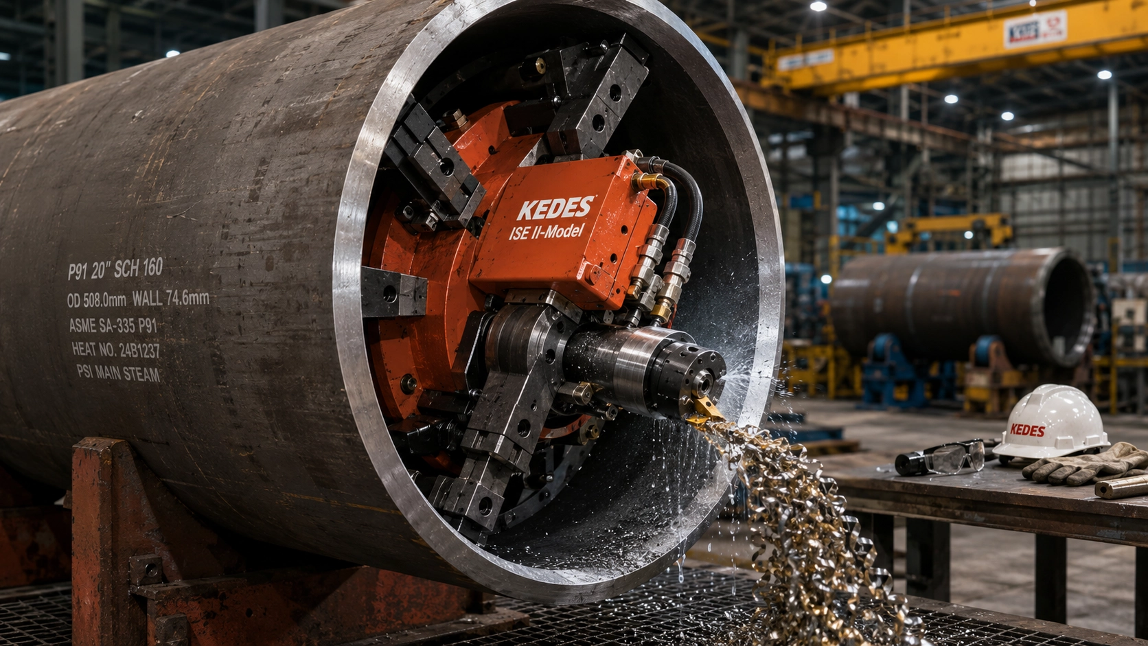 ISE II-Model machining a 75mm wall P91 main steam pipe end at a Chinese boiler fabricator. TiAlN-coated carbide inserts, mist coolant, 0.06mm/rev feed rate. Each insert handles 8–10 joints before indexing. Cutting temperature stays under 60°C throughout — zero metallurgical impact on the bevel face.
When Thermal Cutting Is Unavoidable
I sell cold cutting equipment, and I’d be lying if I said thermal cutting has zero role on a chrome-moly project. Here’s where it legitimately fits:
Initial rough cut on heavy mill lengths. When you receive a 12-meter P91 mill length and need to cut it into three pieces, an oxy-fuel cut for the rough sectioning is acceptable provided you leave at least 30mm extra material on each cut end and cold-machine the final bevel face later. Many fabricators do this — the rough cut goes fast, and the final cold cut is short.
Emergency field repair sectioning. When a leak needs to be removed and the cold cutting machine is in the warehouse, oxy-fuel sectioning of the failed segment is acceptable. The replacement piece’s bevel preparation must still be cold-cut.
Scrap and demolition. Removing P91 piping for replacement, where nothing will be re-welded to the cut faces. Plasma is faster and cheaper. Use it.
What is not acceptable:
- Thermal cutting of the final weld prep surface, ever, on P91/P92/P22 or any chrome-moly intended for service
- “We’ll grind it back” — without a hardness verification step, this fails inspection roughly one joint in ten
- Sharing portable beveling machines between carbon steel and P91 without dedicated inserts — the wrong insert grade wears immediately and produces unacceptable surface finish
The Bottom Line
P91 is unforgiving in a way that carbon steel is not. The metal that comes out of the mill has a designed microstructure that takes hours of controlled heat treatment to produce, and any thermal disturbance at the bevel face is, in effect, partially un-doing that heat treatment in a layer the welding inspector cannot see and the welder cannot recover.
Three rules I give every customer running a P91 or P92 fabrication project:
- No flame, no arc, no plasma on the final weld prep surface. Cold mechanical cutting only. Rough thermal cuts on mill lengths are fine if you leave material to machine away later.
- Specify the right tooling. TiAlN-coated carbide inserts, dedicated to chrome-moly, with proper feed rates. Don’t run P91 with carbon steel tooling and don’t expect carbon steel cycle times.
- Verify the bevel face by hardness before welding. A portable Equotip or UCI hardness tester takes 30 seconds per joint. If the cold-cut bevel reads 200–220 HV, you’re in the clear. If it reads anything higher, something has gone wrong — find it before the welder strikes the arc.
If you’re running a power plant project, a refinery hydrocracker, or any chrome-moly pressure piping where service temperature exceeds 500°C, the cold-cutting argument is not about saving time on the cut. It is about removing a multi-million-dollar failure pathway that nobody on the project will see in the inspection records but everyone will see in the commissioning logs if it goes wrong.
Tell me your P91 spec — pipe size, wall thickness, joint count, project timeline — and I’ll show you the exact machine and tooling setup that puts the hardness data on your side and keeps the 2 AM phone call from happening.
Related reading:
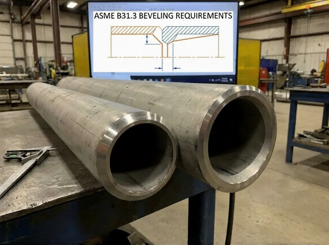
- Stainless Steel Pipe Beveling: Why Heat Is Your Worst Enemy — The sister article for austenitic and duplex grades
- ASME B31.3 Beveling Requirements: The Complete Reference — Code requirements covering P91 in process piping
- Cold Cutting vs Thermal Cutting — The metallurgical case across all materials
- Boiler Tube Beveling Guide — Power plant tube prep including chrome-moly tubing
- Power & Energy Solutions — Full P91/P92 fabrication workflow for boiler and HRSG work
Based on metallurgical post-mortem reports from three commissioning failures (2019, 2022, 2023), hardness data from customer-supplied samples tested by independent labs, and field experience supplying cold cutting equipment to power and petrochemical EPCs since 2015. I manufacture cold cutting machines — that’s my bias. The metallurgy of 9Cr-1Mo-V doesn’t care about my bias: heat the metal above 830°C and quench it, and the microstructure changes whether the data is collected by me or by EPRI. The 2 AM phone call is real. Make it not yours.